Coolcam
2-Channel Wall Switch
NAS-SC01ZE-2
On/Off Power Switch
HW: 16 FW: 2.33
ZM5202
6.81.01
0x0258 (600)
0x0200 (512)
0x102B (4139)
ZC10-19066548
2019-06-20 20:50:50.039759
N/A
Routing Slave
Always On Slave
This product can be included and operated in any Z-Wave™ network with other Z-Wave™ certified devices from other manufacturers and/or other applications.
There have two touch buttons on front panel, anyone can be executed inclusion, exclusion and reset from Z-Wave™ network. The device has 2 main functions: Switch and Timing. There are two ways for controlling the wall switch. The one is touch button to turn on/off switch. Another is Z-Wave command class via network. The device also provides the function of timing, and users can turn off the device by opening this function and setting the time cycle, the setting method of which is shown in "Command Class Configuration".
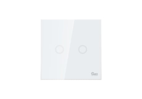
Product Picture


1 - Relay On/Off Status Saved Enable
This parameter defines the on/off status of relay is need to save or not. The status will be saved when relay status is changed if this parameter is set to ‘1’; otherwise the relay status is not saved. The wall switch will restore the relay On/Off status previous when power on againSize: 1 byte
Default: 1
Minimum: 0
Maximum: 0
Possible values
| From | To | Desription |
|---|---|---|
| 0 | 0 | The relay status is not saved when it changes, so it will not return to its previous state after a power failure. |
| 1 | 1 | The relay status is saved each time it changes so that the relay will return to its previous state after a power failure. |
2 - Backlight Enable
This parameter defines the backlight state for touch button. The backlight led is on when wall switch power on if this parameter is set to ‘1’, otherwise the backlight led is off. The default value is ‘1’.Size: 1 byte
Default: 1
Minimum: 0
Maximum: 0
Possible values
| From | To | Desription |
|---|---|---|
| 0 | 0 | the backlight led is off |
| 1 | 1 | the backlight state for touch button. |
3 - Relay On/Off Indicate
This Parameter defines the relay state. The led will be turn on with pink color when the button is touched to turn on relay if this parameter is set to ‘1’; otherwise the led is off. The default value is ‘1’.Size: 1 byte
Default: 1
Minimum: 0
Maximum: 0
Possible values
| From | To | Desription |
|---|---|---|
| 0 | 0 | the led is off. |
| 1 | 1 | the led is on |
4 - Root Device Controlled Settings
This parameter defines which endpoint is mapped to root device (Endpoint 0). The valid values are explained as follows. The default value is ‘1’. 1 – Endpoint 1 is mapped to root endpoint 3 – Both endpoint 1 and 2 are mapped to root endpoint. For example, assumes this parameter is set to ‘1’ (default value). Controller or other devices (such as door/window sensor, motion sensor, etc) that associated the wall switch send a command BASIC_SET = 0xFF to wall switch, the relay in endpoint 1 will be turned on; other relay status will not be changed.Size: 1 byte
Default: 1
Minimum: 0
Maximum: 0
Possible values
| From | To | Desription |
|---|---|---|
| 1 | 1 | Endpoint 1 is mapped to root endpoint |
| 2 | 2 | Endpoint 2 is mapped to root endpoint |
| 3 | 3 | Both endpoint 1 and 2 are mapped to root endpoint. |
5 - Button Switch Function Disable
Setting this configuration as '0' will be disabling to turn on and off the relay by pressed button.Size: 1 byte
Default: 1
Minimum: 0
Maximum: 0
Possible values
| From | To | Desription |
|---|---|---|
| 0 | 0 | Button Switchwill be disabling to turn off |
| 1 | 1 | Button Switchwill be disabling to turn on |
6 - Timer Enable
Setting this configuration as '1' will start the timing function of the plug, and the length of time is determined by the setting of “Configuration: No.7”. This function can only provide the time to turn off device function when the device is open.Size: 1 byte
Default: 0
Minimum: 0
Maximum: 0
Possible values
| From | To | Desription |
|---|---|---|
| 0 | 0 | turn off the timing function of the plug, |
| 1 | 1 | start the timing function of the plug, |
7 - Channel 1 Off Time Setting
This configuration sets the time delay to turn off switch channel 1 when channel 1 is turned on. This configuration is only valid when “Configuration No.6” is set to '1'. Unit: minute.Size: 2 bytes
Default: 0
Minimum: 0
Maximum: 0
Possible values
| From | To | Desription |
|---|---|---|
| 0 | 32767 | This configuration sets the time delay to turn off switch channel 1 when channel 1 is turned on. |
8 - Channel 2 Off Time Setting
This configuration sets the time delay to turn off switch channel 2 when channel 2 is turned on. This configuration is only valid when “Configuration No.6” is set to '1'. Unit: minute.Size: 2 bytes
Default: 0
Minimum: 0
Maximum: 0
Possible values
| From | To | Desription |
|---|---|---|
| 0 | 32767 | This configuration sets the time delay to turn off switch channel 2 when channel 2 is turned on. |
1、 Set Z-Wave™ Controller into inclusion mode 2、 Power on the device. 3、 Touch any button 3 times within 1s. 4、 The device will be entered into inclusion mode automatically.
1、 Set Z-Wave™ Controller into exclusion mode 2、 Power on the device. 3、 Touch any button 3 times within 1s 4、 The Device will be entered into exclusion mode automatically.
1、 Power on the device. 2、 Keep holding touched the button for 10s until the led turn to red, then release. Please include a request to use the reset procedure only when the primary controller is missing or inoperable.
| Type | Value(s) |
|---|
| Group | Type |
|---|---|
| Access Control | (Refer to parameters): State idle |
| Sensor type |
|---|
| General Purpose |