Aeotec
Smart Switch 7
ZW175-C16
On/Off Power Switch
HW: 175 FW: 1.02
ZM5101
6.81.03
0x0371 (881)
0x0003 (3)
0x00AF (175)
ZC10-19066544
2019-06-14 16:44:25.682396
N/A
Enhanced 232 Slave
Always On Slave
A small but powerful switch with energy metering function.
1. Elegant appearance, small size, easy to use, friendly operation. 2. Support power metering function, with high measurement accuracy, and more accurate knowledge of the power consumption of the load. 3. Support over-current, over-load and over-heat protection, which is more secure and reliable. 4. Support scene personalization and is more intelligent. 5. Support Night Light Mode to reduce light pollution. 6. Support S2 Security, which is safer and more reliable. 7. Support SmartStart, making inclusion more convenient.
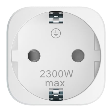
Product Picture


4 - Over-load protection
Define a threshold power and automatically turn off switch when the load connected bypasses the maximum allowed power regardless of always on setting. Over-load protection will be active if the load power exceeds the setting and lasts for more than 30s. If be active, Indicator Light will become red light blinking and the product will send out Notification Report (Over-load detected), and disable the function that manually or RF control the switch state until users set Protection State to be unprotected through the Gateway or Controller. Even power off will still keep Protection State.Size: 2 bytes
Default: 2415
Minimum: 0
Maximum: 0
Possible values
| From | To | Desription |
|---|---|---|
| 0 | 0 | Disable over-load protection |
| 1 | 2415 | Threshold power is 1-2145W |
8 - Alarm Response
Enabled by (Alarm Settings), and determines what the switch does in the case an alarm is triggered. When receives any alarm enabled by Alarm Settings, Indicator Light will keep blinking based on Parameter 0x12 (18). It will prohibit user from manually or RF control the switch state until the alarm is disable.Size: 1 byte
Default: 0
Minimum: 0
Maximum: 0
Possible values
| From | To | Desription |
|---|---|---|
| 0 | 0 | Disable, no reaction to alarm settings |
| 1 | 1 | Switch is ON |
| 2 | 2 | Switch is OFF |
| 3 | 3 | Switch will turn ON in 5 seconds, and then turn OFF in 5 seconds in a cycle until user disables the alarm manually |
9 - Alarm Settings
Determine if alarms are enabled in Switch, and what Switch will react to which alarm. The format of the parameter is Bit field (Checkboxes). The parameter MUST be treated as a bit field where each individual bit can be set or reset. A graphical configuration tool SHOULD present this parameter as a series of checkboxes. Please refer to the manual for more details about supported Notification Type and Notification Event.Size: 2 bytes
Default: 0
Minimum: 0
Maximum: 0
Possible values
| From | To | Desription |
|---|---|---|
| 1 | 1 | Access Control trigger state |
| 256 | 256 | Smoke Alarm |
| 512 | 512 | CO Alarm |
| 1024 | 1024 | CO2 Alarm |
| 2048 | 2048 | Heart Alarm |
| 4096 | 4096 | Water Alarm |
| 8192 | 8192 | Access Control |
| 16384 | 16384 | Home Security |
10 - Setting to disable alarm
Determines the method of disabling the alarm of the device. Note: Power off will also disable the alarm response without any limitation.Size: 2 bytes
Default: 0
Minimum: 0
Maximum: 0
Possible values
| From | To | Desription |
|---|---|---|
| 0 | 0 | Can be disabled by 3x tapping Action Button within 1 second |
| 1 | 1 | Can be disabled when receives a State Idle corresponding to the alarm. Note: If Access Control is enable, it also can be disabled when receives the reversal state of window/door. |
| 10 | 255 | Sets the duration of the alarm in seconds(i.e. Customer sets this setting to 50, the alarm state of the Switch will disable after 50 seconds) |
18 - LED blinking frequency
When receiving the enable Alarm, it will flash according to the blink frequency configured by this parameter until the Alarm is disable. Brightness level and color is based on current indicator. If the value of brightness level and color is 0, it will flash based on last visible color.Size: 1 byte
Default: 2
Minimum: 0
Maximum: 0
Possible values
| From | To | Desription |
|---|---|---|
| 1 | 9 | Set amount of blinks per seconds. |
19 - Start or stop LED blinking.(Write Only)
The parameter can be used to test the effect of LED blinking.Size: 2 bytes
Default: 0
Minimum: 0
Maximum: 0
Possible values
| From | To | Desription |
|---|---|---|
| 0 | 0 | Stop blinking. |
| 1 | 255 | Set the duration and start the blinking process. * This sets the timeframe of blinking in seconds. * Once the duration ends, the blinking will stop. |
20 - Action in case of power out.
Action in case of power out.Size: 1 byte
Default: 0
Minimum: 0
Maximum: 0
Possible values
| From | To | Desription |
|---|---|---|
| 0 | 0 | Last status |
| 1 | 1 | Switch is on |
| 2 | 2 | Switch is off |
80 - Configure what command will be sent via Lifeline when switch state has changed.
Configure what command will be sent via Lifeline when switch state has changed.Size: 1 byte
Default: 2
Minimum: 0
Maximum: 0
Possible values
| From | To | Desription |
|---|---|---|
| 0 | 0 | None |
| 1 | 1 | Basic Report |
| 2 | 2 | Binary Switch Report |
81 - Load Indicator Mode setting.
Note: Configuring brightness and color of Indicator Light in different time/status of different modes will be saved in the current setting mode. Please refer to the manual for more details.Size: 1 byte
Default: 2
Minimum: 0
Maximum: 0
Possible values
| From | To | Desription |
|---|---|---|
| 0 | 0 | Disable Mode |
| 1 | 1 | Night Light Mode |
| 2 | 2 | ON/OFF Mode |
82 - Configure the enable and disable time of Night Light Mode
If you want to set Night Light Mode to be enable at 19:00 at night and disable at 07:30 in the morning, you just need to configure: Value1=0x13, Value2=0x00, Value3=0x07, Value4=0x1E.Size: 4 bytes
Default: 301991936
Minimum: 0
Maximum: 0
Possible values
| From | To | Desription |
|---|---|---|
| 0 | 2147483647 | Value1=Enable Hour, Value2=Enable Minute, Value3=Disable Hour, Value4=Disabale Minute |
91 - Threshold Power (W) for inducing automatic report.
Threshold Power (W) for inducing automatic report.Size: 2 bytes
Default: 0
Minimum: 0
Maximum: 0
Possible values
| From | To | Desription |
|---|---|---|
| 0 | 0 | Disable |
| 1 | 2300 | 1-2300W |
92 - Threshold Power Consumption (kWh) for inducing automatic report.
Threshold Power Consumption (kWh) for inducing automatic report.Size: 2 bytes
Default: 0
Minimum: 0
Maximum: 0
Possible values
| From | To | Desription |
|---|---|---|
| 0 | 0 | Disable |
| 1 | 10000 | 1-10000kWh |
93 - Threshold Current (A) for inducing automatic report.
Threshold Current (A) for inducing automatic report.Size: 1 byte
Default: 0
Minimum: 0
Maximum: 0
Possible values
| From | To | Desription |
|---|---|---|
| 0 | 0 | Disable |
| 1 | 100 | 0.1-10A. Unit is 0.1A. |
101 - Configure which meter reading will be periodically report via Lifeline.
The format of the parameter is Bit field (Checkboxes). The parameter MUST be treated as a bit field where each individual bit can be set or reset. A graphical configuration tool SHOULD present this parameter as a series of checkboxes. Note: The sending frequency is related to Configuration Parameter 0x6F (111).Size: 4 bytes
Default: 15
Minimum: 0
Maximum: 0
Possible values
| From | To | Desription |
|---|---|---|
| 1 | 1 | Power Consumption |
| 2 | 2 | Power |
| 4 | 4 | Voltage |
| 8 | 8 | Current |
111 - Configure the sending frequency of Meter Report.
Configure the sending frequency of Meter Report.Size: 4 bytes
Default: 600
Minimum: 0
Maximum: 0
Possible values
| From | To | Desription |
|---|---|---|
| 0 | 0 | Disable |
| 600 | 2592000 | 600-2592000s. (10minute-30day) |
255 - Factory Reset or Initialization (Write Only)
Factory Reset or Initialization (Write Only)Size: 1 byte
Default: 0
Minimum: 0
Maximum: 0
Possible values
| From | To | Desription |
|---|---|---|
| 1431655765 | 1431655765 | Factory Reset: Restore the product to factory settings and remove from the network. |
| 0 | 0 | Initialization: Initialize all configuration parameters to default values. |
This product supports Security 2 Command Class. While a Security S2 enabled Controller is needed in order to fully use the security feature. This product can be included and operated in any Z-Wave network with other Z-Wave certified devices from other manufacturers and/or other applications. All non-battery operated nodes within the network will act as repeaters regardless of vendor to increase reliability of the network. (1) SmartStart Learn Mode SmartStart enabled products can be added into a Z-Wave network by scanning the Z-Wave QR Code present on the product with a controller providing SmartStart inclusion. No further action is required and the SmartStart product will be added automatically within 10 minutes of being switched on in the network vicinity. Indicator Light will become flash white light for 1s indicating the product has been powered, and then become flash blue light indicating SmartStart Learn Mode starts. It will become constantly bright yellow light after being assigned a NodeID. If Adding succeeds, it will bright blue light for 2s and become Load Indicator Mode. If Adding fails, it will bright red light for 2s and turn back to breathing blue light and then start SmartStart Learn Mode again. Note: The label of QR Code on the product and package are used for SmartStart Inclusion. The Z-Wave DSK Code is at bottom of the package. Please do not remove or damage them. (2) Classic Inclusion Learn Mode 1. Set your Z-Wave Controller into its 'Add Device' mode in order to add the product into your Z-Wave system. Refer to the Controller's manual if you are unsure of how to perform this step. 2. Make sure the product is powered. If not, plug it into a wall socket and power on; its LED will be breathing blue light all the time. 3. Click Action Button once, it will quickly flash blue light for 30 seconds until it is added into the network. It will become constantly bright yellow light after being assigned a NodeID. 4. If your Z-Wave Controller supports S2 encryption, enter the first 5 digits of DSK into your Controller's interface if /when requested. The DSK is printed on its housing. 5. If Adding fails, it will bright red light for 2s and then become breathing blue light; repeat steps 1 to 4. Contact us for further support if needed. 6. If Adding succeeds, it will bright blue light for 2s and then turn to Load Indicator Mode. Now, this product is a part of your Z-Wave home control system. You can configure it and its automations via your Z-Wave system; please refer to your software's user guide for precise instructions. Note: If Action Button is clicked again during the Classic Inclusion Learn Mode, the Classic Inclusion Learn Mode will exit. At the same time, Indicator Light will bright red light for 2s, and then become breathing blue light.
1. Set your Z-Wave Controller into its 'Remove Device' mode in order to remove the product from your Z-Wave system. Refer to the Controller's manual if you are unsure of how to perform this step. 2. Make sure the product is powered. If not, plug it into a wall socket and power on. 3. Click Action Button 2 times quickly; it will bright violet light, up to 2s. 4. If Removing fails, it will bright red light for 2s and then turn back to Load Indicator Mode; repeat steps 1 to 3. Contact us for further support if needed. 5. If Removing succeeds, it will become breathing blue light. Now, it is removed from Z-Wave network successfully.
If the primary controller is missing or inoperable, you may need to reset the device to factory settings. Make sure the product is powered. If not, plug it into a wall socket and power on. To complete the reset process manually, press and hold the Action Button for at least 15s and then release. The LED indicator will become breathing blue light, which indicates the reset operation is successful. Otherwise, please try again. Contact us for further support if needed. Note: 1. This procedure should only be used when the primary controller is missing or inoperable. 2. Factory Reset will: (a) Remove the product from Z-Wave network; (b) Delete the Association setting; (c) Restore the configuration settings to the default.
Regardless of the state of the product, when over-current or over-load detected, it will automatically TURN OFF switch and set Local Protection State to be 2 and RF Protection State to be 1, and start red light blinking. Users can’t manually or RF control the switch state until setting the Protection State to be unprotected through the Gateway or Controller, even power off will still keep Protection State.
| Type | Value(s) |
|---|
| Group | Type |
|---|---|
| Power Management | (Refer to parameters): State idle |
| System | (Refer to parameters): State idle |
| Sensor type |
|---|
| Power |
| Voltage |
| Current |
| Meter type |
|---|
| Electric Meter Consumption |