RCS
Thermostat
TBZ500
Thermostat - HVAC
HW: 1 FW: 1.00:02.16
ZM5202
6.51.06
0x0010 (16)
0x5442 (21570)
0x543A (21562)
ZC10-19076651
2019-07-02 20:48:25.494301
N/A
Routing Slave
Listening Sleeping Slave
Yes
The TBZ500 Z-Wave Plus Thermostat is a programmable, Z-Wave communicating thermostat.
The TBZ500 Z-Wave Plus Thermostat is a programmable, Z-Wave communicating thermostat. It can be powered using 24VAC, or using four (4) AA batteries. Using Z-Wave technology, end users have the ability to use most compatible Z-Wave hubs/controllers to operate and animate the thermostat, configure programming settings, as well as to display current conditions in the home or office.
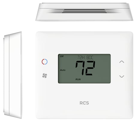
Product Picture


1 - System Type
Sets the system type. Standard or Heat PumpSize: 1 byte
Default: 0
Minimum: 0
Maximum: 0
Possible values
| From | To | Desription |
|---|---|---|
| 0 | 0 | Standard |
| 1 | 1 | Heat Pump |
2 - Fan Type
Sets the fan type. Electric (Fan w/Heat) or Gas (no Fan w/Heat)Size: 1 byte
Default: 0
Minimum: 0
Maximum: 0
Possible values
| From | To | Desription |
|---|---|---|
| 0 | 0 | Gas (no fan w/Heat |
| 1 | 1 | Electric (Fan w/Heat |
3 - Change Over Type
Sets change over type. Change over with cool or change over with heat.Size: 1 byte
Default: 0
Minimum: 0
Maximum: 0
Possible values
| From | To | Desription |
|---|---|---|
| 0 | 0 | CO w/Cool |
| 1 | 1 | CO w/Heat |
4 - 2nd Stage Heat Enable
Enables or disables the second stage heat operation.Size: 1 byte
Default: 0
Minimum: 0
Maximum: 0
Possible values
| From | To | Desription |
|---|---|---|
| 0 | 0 | Disabled |
| 1 | 1 | Enabled |
5 - Aux Heat Enable
Enables or disables aux heat operation.Size: 1 byte
Default: 1
Minimum: 0
Maximum: 0
Possible values
| From | To | Desription |
|---|---|---|
| 0 | 0 | Disabled |
| 1 | 1 | Enabled |
6 - 2nd Stage Cool Enable
Enables or disables the second stage cool operation.Size: 1 byte
Default: 0
Minimum: 0
Maximum: 0
Possible values
| From | To | Desription |
|---|---|---|
| 0 | 0 | Disabled |
| 1 | 1 | Enabled |
7 - C/F Type
Enables changing from Centigrade to Fahrenheit or vice versa.Size: 1 byte
Default: 1
Minimum: 0
Maximum: 0
Possible values
| From | To | Desription |
|---|---|---|
| 0 | 0 | Centigrade |
| 1 | 1 | Fahrenheit |
8 - MOT
Sets the Minimum Off Time (MOT) delay before another heating/cooling cycle can begin. Provides compressor short cycle protection. “Wait” is displayed on screen when active.Size: 1 byte
Default: 5
Minimum: 0
Maximum: 0
Possible values
| From | To | Desription |
|---|---|---|
| 5 | 9 | Minutes |
9 - MRT
Sets the Minimum Run Time (MRT) delay before a heating/cooling cycle can turn off. Sets heating/cooling cycle time. Prevents rapid on/off cycling.Size: 1 byte
Default: 3
Minimum: 0
Maximum: 0
Possible values
| From | To | Desription |
|---|---|---|
| 3 | 9 | Minutes |
10 - Setpoint H/C Delta
Sets the minimum separation between heating and cooling setpoints. NOTE: Attempts to lower cooling setpoint below the heating setpoint will PUSH the heating setpoint down to maintain this separation. The same applies to setting the heating setpoint above the cooling setpoint, it will PUSH the cooling setpoint up to maintain the setpoint delta separation.Size: 1 byte
Default: 3
Minimum: 0
Maximum: 0
Possible values
| From | To | Desription |
|---|---|---|
| 3 | 15 | Degrees |
11 - H Delta Stage 1 ON
Sets the delta from setpoint that stage 1 heating startsSize: 1 byte
Default: 1
Minimum: 0
Maximum: 0
Possible values
| From | To | Desription |
|---|---|---|
| 1 | 6 | Degrees |
12 - H Delta Stage 1 OFF
Sets the delta from setpoint that stage 1 heating stops. Stage 1 turns off at setpoint + Delta Stage 1.Size: 1 byte
Default: 0
Minimum: 0
Maximum: 0
Possible values
| From | To | Desription |
|---|---|---|
| 0 | 5 | Degrees |
13 - H Delta Stage 2 ON
Sets the delta from setpoint that stage 2 heating startsSize: 1 byte
Default: 2
Minimum: 0
Maximum: 0
Possible values
| From | To | Desription |
|---|---|---|
| 2 | 7 | Degrees |
14 - H Delta Stage 2 OFF
Sets the delay from setpoint that stage 2 heating stops. Stage 2 turns off at setpoint + Delta Stage 2.Size: 1 byte
Default: 0
Minimum: 0
Maximum: 0
Possible values
| From | To | Desription |
|---|---|---|
| 0 | 6 | Degrees |
15 - H Delta Aux ON
Sets the delta from setpoint that stage 3 heating startsSize: 1 byte
Default: 3
Minimum: 0
Maximum: 0
Possible values
| From | To | Desription |
|---|---|---|
| 3 | 8 | Degrees |
16 - H Delta Aux OFF
Sets the delta from setpoint that stage 3 heating stops. Stage 3 turns off at setpoint + Delta Stage 3Size: 1 byte
Default: 0
Minimum: 0
Maximum: 0
Possible values
| From | To | Desription |
|---|---|---|
| 0 | 7 | Degrees |
17 - C Delta Stage 1 ON
Sets the delta from setpoint that stage 1 cooling starts.Size: 1 byte
Default: 1
Minimum: 0
Maximum: 0
Possible values
| From | To | Desription |
|---|---|---|
| 1 | 6 | Degrees |
18 - C Delta Stage 1 OFF
Sets the delta from setpoint that stage 1 cooling stops. Stage 1 turns off at setpoint - Delta Stage 1Size: 1 byte
Default: 0
Minimum: 0
Maximum: 0
Possible values
| From | To | Desription |
|---|---|---|
| 0 | 5 | Degrees |
19 - C Delta Stage 2 ON
Sets the delta from setpoint that stage 2 cooling starts.Size: 1 byte
Default: 2
Minimum: 0
Maximum: 0
Possible values
| From | To | Desription |
|---|---|---|
| 2 | 7 | Degrees |
20 - C Delta Stage 2 OFF
Sets the delta from setpoint that stage 2 cooling stops. Stage 2 turns off at setpoint - Delta Stage 2.Size: 1 byte
Default: 0
Minimum: 0
Maximum: 0
Possible values
| From | To | Desription |
|---|---|---|
| 0 | 6 | Degrees |
21 - Mechanical Status
Thermostat Mechanical status config parameters. MECH_H1 0x0001 MECH_H2 0x0002 MECH_H3 0x0004 MECH_C1 0x0008 MECH_C2 0x0010 PHANTOM_F 0x0020 MECH_F 0x0040 MANUAL_F 0x0080 reserved 0x0100Size: 2 bytes
Default: 0
Minimum: 0
Maximum: 0
Possible values
| From | To | Desription |
|---|---|---|
| 1 | 1 | MECH_H1 |
| 2 | 2 | MECH_H2 |
| 4 | 4 | MECH_H3 |
| 8 | 8 | MECH_C1 |
| 16 | 16 | MECH_C2 |
| 32 | 32 | PHANTOM_F |
| 64 | 64 | MECH_F |
| 128 | 128 | MANUAL_F |
| 256 | 256 | reserved |
22 - SCP Status
Thermostat State Config Parameters STATE_HEAT 0x01 STATE_COOL 0x02 STATE_2ND 0x04 STATE_3RD 0x08 STATE_FAN 0x10 STATE_LAST 0x20 STATE_MOT 0x40 STATE_MRT 0x80Size: 1 byte
Default: 0
Minimum: 0
Maximum: 0
Possible values
| From | To | Desription |
|---|---|---|
| 1 | 1 | STATE_HEAT |
| 2 | 2 | STATE_COOL |
| 4 | 4 | STATE_2ND |
| 8 | 8 | STATE_3RD |
| 16 | 16 | STATE_FAN |
| 32 | 32 | STATE_LAST |
| 64 | 64 | STATE_MOT |
| 128 | 128 | STATE_MRT |
23 - Autosend Enable Bits
When set, the corresponding report is sent out unsolicited when a changed node is detected to the nodes in the association list. TEMPERATURE (CC_SENSOR_MULTILEVEL) 0x0001 SETPOINT H (CC_THERMOSTAT_SETPOINT) 0x0002 SETPOINT C (CC_THERMOSTAT_SETPOINT) 0x0004 MODE (CC_THERMOSTAT_MODE) 0x0008 FANMODE (CC_ THERMOSTAT_FAN_MODE) 0x0010 FANSTATE (CC_THERMOSTAT_FAN_STATE) 0x0020 OPERATING STATE (CC_THERMOSTAT_OPERATING STATE) 0x0040 SCHEDENABLE (CC_CONFIGURATION #38) 0x0080 SETBACK (CC_ CONFIGURATION #40) 0x0100 RUNHOLD (CC_CONFIGURATION #39) 0x0200 DISPLAYLOCK (CC_CONFIGURATION #24) 0x0400 BATTERY 6 (CC_BATTERY) 0x2000 MECH STATUS (CC_CONFIGURATION # 21) 0x4000 SCP STATUS (CC_CONFIGURATION # 22) 0x8000Size: 2 bytes
Default: 8223
Minimum: 0
Maximum: 0
Possible values
| From | To | Desription |
|---|---|---|
| 1 | 1 | TEMPERATURE (CC_SENSOR_MULTILEVEL) |
| 2 | 2 | SETPOINT H (CC_THERMOSTAT_SETPOINT) |
| 4 | 4 | SETPOINT C (CC_THERMOSTAT_SETPOINT) |
| 8 | 8 | MODE (CC_THERMOSTAT_MODE) |
| 16 | 16 | FANMODE (CC_ THERMOSTAT_FAN_MODE) |
| 32 | 32 | FANSTATE (CC_THERMOSTAT_FAN_STATE) |
| 64 | 64 | OPERATING STATE (CC_THERMOSTAT_OPERATING STATE) |
| 128 | 128 | SCHEDENABLE (CC_CONFIGURATION #38) |
| 256 | 256 | SETBACK (CC_ CONFIGURATION #40) |
| 512 | 512 | RUNHOLD (CC_CONFIGURATION #39) |
| 1024 | 1024 | DISPLAYLOCK (CC_CONFIGURATION #24) |
| 8192 | 8192 | BATTERY 6 (CC_BATTERY) |
| 16384 | 16384 | MECH STATUS (CC_CONFIGURATION # 21) |
| 32768 | 32768 | SCP STATUS (CC_CONFIGURATION # 22) |
24 - Display Lock
Sets locking and unlocking of control of the display screen.Size: 1 byte
Default: 0
Minimum: 0
Maximum: 0
Possible values
| From | To | Desription |
|---|---|---|
| 0 | 0 | Unlocked |
| 1 | 1 | Locked |
26 - Backlight Timer
Sets the time the thermostat backlight will go out after no button presses to conserve battery power.Size: 1 byte
Default: 20
Minimum: 0
Maximum: 0
Possible values
| From | To | Desription |
|---|---|---|
| 10 | 30 | Seconds |
33 - Max Heat Setpoint
Sets the maximum heating setpoint value. Will not ramp or accept setpoints higher than this maximum. 30F - 109FSize: 1 byte
Default: 90
Minimum: 0
Maximum: 0
Possible values
| From | To | Desription |
|---|---|---|
| 30 | 109 | Degrees |
34 - Min Cool Setpoint
Sets the minimum cooling setpoint value. 33F - 112FSize: 1 byte
Default: 60
Minimum: 0
Maximum: 0
Possible values
| From | To | Desription |
|---|---|---|
| 33 | 112 | Degrees |
38 - Schedule Enable
Enables or disables the use of schedules.Size: 1 byte
Default: 0
Minimum: 0
Maximum: 0
Possible values
| From | To | Desription |
|---|---|---|
| 0 | 0 | Disabled |
| 1 | 1 | Enabled |
39 - Run/Hold Mode
Sets hold and run functionality. Hold locks the current temperature indefinitely. Run resumes the preprogrammed schedule.Size: 1 byte
Default: 0
Minimum: 0
Maximum: 0
Possible values
| From | To | Desription |
|---|---|---|
| 0 | 0 | Hold |
| 1 | 1 | Run |
40 - Setback Mode
Enables setback or Un-Occupied mode. Temperature setback reduces how often the heating or cooling system operates by allowing the temperature in a home to drift to a lower (heating mode) or higher (cooling mode) temperature.Size: 1 byte
Default: 0
Minimum: 0
Maximum: 0
Possible values
| From | To | Desription |
|---|---|---|
| 0 | 6 | Degrees |
| 0 | 0 | No Setback |
| 2 | 2 | Un-Occupied Mode |
41 - Un-Occupied HSP
Sets thermostat heating setpoint temperature when un-occupied. 30F - 109FSize: 1 byte
Default: 62
Minimum: 0
Maximum: 0
Possible values
| From | To | Desription |
|---|---|---|
| 30 | 109 | Degrees |
42 - Un-Occupied HSP
Sets thermostat cooling setpoint temperature when un-occupied. 33F - 112FSize: 1 byte
Default: 80
Minimum: 0
Maximum: 0
Possible values
| From | To | Desription |
|---|---|---|
| 33 | 112 | Degrees |
43 - Remote Sensor 1 Node Number
Sets remote sensor 1 node number. 0=disabled.Size: 1 byte
Default: 0
Minimum: 0
Maximum: 0
Possible values
| From | To | Desription |
|---|---|---|
| 0 | 252 | node number |
46 - Remote Sensor 1 Temperature
Displays remote sensor 1 Temperature.Size: 1 byte
Default: 0
Minimum: 0
Maximum: 0
Possible values
| From | To | Desription |
|---|---|---|
| 0 | 0 | N/A |
48 - Internal Sensor Temp Offset
Sets Internal Sensor Temp Offset. -7 to 7Size: 1 byte
Default: 0
Minimum: 0
Maximum: 0
Possible values
| From | To | Desription |
|---|---|---|
| -7 | 7 | Degrees |
49 - R1 Sensor Temp Off set
Sets R1 Sensor Temp Offset. -7 to 7 degreesSize: 1 byte
Default: 0
Minimum: 0
Maximum: 0
Possible values
| From | To | Desription |
|---|---|---|
| -7 | 7 | Degrees |
52 - Filter Timer (hours)
Sets Filter Timer (hours). 0 to 4000Size: 2 bytes
Default: 0
Minimum: 0
Maximum: 0
Possible values
| From | To | Desription |
|---|---|---|
| 0 | 4000 | Hours |
53 - Filter Timer Max (hrs)
Sets Filter Timer Max (hrs). 0 to 4000.Size: 2 bytes
Default: 300
Minimum: 0
Maximum: 0
Possible values
| From | To | Desription |
|---|---|---|
| 0 | 4000 | Hours |
54 - Heat Timer (hours)
Sets Heat Timer (hours). 0 to 4000.Size: 2 bytes
Default: 0
Minimum: 0
Maximum: 0
Possible values
| From | To | Desription |
|---|---|---|
| 0 | 4000 | Hours |
55 - Cool Timer (hours)
Sets Cool Timer (hours). 0 to 4000.Size: 2 bytes
Default: 0
Minimum: 0
Maximum: 0
Possible values
| From | To | Desription |
|---|---|---|
| 0 | 4000 | Hours |
61 - Fan Purge Heat
Sets Fan Purge Heat. Sets the system blower delay off time after a heat call ends (fan purge). 0 to 90 Seconds.Size: 1 byte
Default: 0
Minimum: 0
Maximum: 0
Possible values
| From | To | Desription |
|---|---|---|
| 0 | 90 | Seconds |
62 - Fan Purge Cool
Sets Fan Purge Cool. Sets the system blower delay off time after a cool call ends (fan purge). 0 to 90 SecondsSize: 1 byte
Default: 0
Minimum: 0
Maximum: 0
Possible values
| From | To | Desription |
|---|---|---|
| 0 | 90 | Seconds |
186 - 0xBA
Temperature Delta Autosend Threshold (how many degree change from last autosend). 1 to 5 degrees.Size: 1 byte
Default: 2
Minimum: 0
Maximum: 0
Possible values
| From | To | Desription |
|---|---|---|
| 1 | 5 | Degrees |
187 - 0xBB
Periodic Temperature Send Interval (min). 0=Disabled. 1-120 minutes.Size: 1 byte
Default: 0
Minimum: 0
Maximum: 0
Possible values
| From | To | Desription |
|---|---|---|
| 1 | 120 | Minutes |
194 - RH Delta Autosend Threshold
Sets how often a relative humidity report is sent based on percent change.Size: 1 byte
Default: 5
Minimum: 0
Maximum: 0
Possible values
| From | To | Desription |
|---|---|---|
| 1 | 50 | Percent |
195 - Periodic RH Send Interval
Sets how often a relative humidity report is sent based on time. 0=Disabled, 1-120 minutes.Size: 1 byte
Default: 0
Minimum: 0
Maximum: 0
Possible values
| From | To | Desription |
|---|---|---|
| 0 | 120 | Minutes |
Inclusion is started by putting the controller into add node state and performing the General Programming Procedure. As part of the process, the thermostat sends a node information frame at normal power. Low power inclusion is not possible. General Programming Procedure (for controllers supporting the thermostat device class): 1. Set your primary controller to Include, add or Install mode, to add the thermostat as a node on your network (see your controller’s user manual for detailed instructions). 2. Press any button to take thermostat out of sleep mode. 3. Press and hold FAN button for 5 seconds. SETUP will be displayed in the status display line. 4. Scroll to “Z-Wave” using  buttons. Press SELECT. 5. When prompted by your Z-Wave controller, Press the YES button in the Z-Wave Install screen. 6. Press SELECT (mode button) to add thermostat to network. 7. Display line should fl ash WAIT then SUCCESS if Z-Wave connection is made. 8. If Z-Wave does not connect to controller, WAIT, then FAIL will flash in status display line. 9. If thermostat fails to connect, repeat Steps three (3) thru (7) to re-try connecting. Your controller will indicate the thermostat was successfully added to its network (see your controller’s user manual for details). Also, you can check if the thermostat was successfully added to the network by checking the ZHID (Home ID) and ZNID (Node ID) located in the Thermostat Info screen. For other specific tasks such as adding the thermostat to Scenes or Groups, or deleting the thermostat from an existing network, refer to the Z-Wave controller instructions.
Exclusion is started by putting the controller into remove node state and performing the General Programming Procedure. As part of the process, the thermostat sends a node information frame at normal power. Low power exclusion is not possible.
Factory Reset WARNING: Please use this procedure only when the Z-Wave Primary Controller is missing or otherwise inoperable. To reset the TBZ500's Z-Wave parameters to Factory Settings (both Z-Wave and HVAC settings): 1. Remove power from the TBZ500. 2. Power up the TBZ500 and when you see TBZ500 on the screen, hold down the MODE and FAN buttons simultaneously. 3. Release when RESET appears on the Status Line. 4. Once the TBZ500 resets the Z-Wave and HVAC settings, a DONE confirmation message will appear on the screen before the thermostat self-reboots.
Test Mode - shortens the system built-in delays (like MOT and MRT) Aux Heat Enable (Heat Pump Systems only) - Enables the auxiliary heat operation. 2nd Stage Heat Enable - Enables the second stage heat operation 2nd Stage Cool Enable - Enables the second stage cool operation Minimum run time - Sets the Minimum Run Time (MRT) delay before a heating/cooling cycle can turn off. Prevents rapid on/off cycling. Minimum Off Time - Sets the Minimum Off Time (MOT) delay before another heating/cooling cycle can begin. Provides compressor short cycle protection. “Wait” is displayed on screen when active. Heat Setpoint Max. - Sets the maximum heating setpoint value. Will not ramp or accept setpoints higher than this maximum Cool Setpoint Min. - Sets the maximum heating setpoint value Heat Blower Off Delay - Sets the system blower delay off time after a heat call ends (fan purge) Cool Blower Off Delay - Sets the system blower delay off time after a cool call ends (fan purge) Heat - Cool Delta - Sets the minimum separation between heating and cooling setpoints. Heating Stage 1 on Threshold - Sets the delta from setpoint that stage 1 heating starts. Heating Stage 1 Off Threshold - Sets the delta from setpoint that stage 1 heating stops. Heating Stage 2 On Threshold - Sets the delta from setpoint that stage 2 heating starts. Heating Stage 2 Off Threshold - Sets the delay from setpoint that stage 2 heating stops. Aux Heat On Threshold - Sets the delta from setpoint that stage 3 heating starts. Aux Heat Off Threshold - Sets the delta from setpoint that stage 3 heating stops. Cooling Stage 1 On Threshold - Sets the delta from setpoint that stage 1 cooling starts. Cooling Stage 1 Off Threshold - Sets the delta from setpoint that stage 1 cooling stops. Cooling Stage 2 On Threshold - Sets the delta from setpoint that stage 2 cooling starts. Cooling Stage 2 Off Threshold - Sets the delta from setpoint that stage 2 cooling stops. Restore Defaults - Restores all settings to factory defaults.
| Type | Value(s) |
|---|
| Sensor type |
|---|
| Air Temperature |
| Humidity |