FIBARO
FIBARO Wall Plug
FGWPx-102
On/Off Power Switch
HW: 2 FW: 3.02:03.02
ZM5202
6.51.07
0x010F (271)
0x0602 (1538)
0x4003 (16387)
ZC10-19076607
2019-07-01 22:20:45.755691
N/A
Enhanced 232 Slave
Always On Slave
FIBARO Wall Plug is a Z-Wave controlled plug-in switch with the ability to measure power and energy consumption.
FIBARO Wall Plug is a remotely controlled plug-in switch with the ability to measure power and energy consumption. It uses a LED frame to visualize the current load and operating mode with color changing illumination. FIBARO Wall Plug makes it possible to control electrical devices in a convenient and maintenance-free way. Main features of FIBARO Wall Plug: - Compatible with any Z-Wave or Z-Wave Plus Controller. - Supports Z-Wave network Security Modes: S0 with AES-128 encryption and S2 with PRNG-based encryption. - Extremely easy installation - simply plug the device into the mains socket. - Works as a Z-Wave signal repeater. - Active power and energy consumption metering for plugged device. - Current value of the load and operating mode are indicated by the multi-color LED frame.
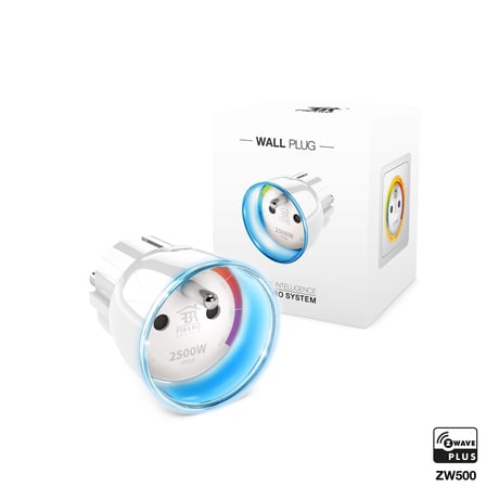
Product Picture


1 - Always On function
Once activated, Wall Plug will keep the connected device constantly ON, will stop reacting to alarm frames or pushing the B-button. “Always On” function turns the Wall Plug into a power and energy meter. Connected device will not be turned off upon receiving an alarm frame from another Z-Wave device (parameter 31 will be ignored). In “Always on” mode, connected device may be turned off only after user defined power has been exceeded (parameter 3). In such a case, connected device can be turned on again by pushing the B-button or sending a control frame. By default, overload protection is inactive.Size: 1 byte
Default: 0
Minimum: 0
Maximum: 0
Possible values
| From | To | Desription |
|---|---|---|
| 0 | 0 | function inactive |
| 1 | 1 | function activated |
2 - Remember device status after a power failure
This parameter determines how the Wall Plug will react in the event of power supply failure (e.g. taking out from the electrical outlet). After the power supply is back on, the Wall Plug can be restored to previous state or remain switched off. This parameter is ignored in „Always On” mode - the device automatically turns ON after plugging it into the socket.Size: 1 byte
Default: 1
Minimum: 0
Maximum: 0
Possible values
| From | To | Desription |
|---|---|---|
| 0 | 0 | device remains switched off |
| 1 | 1 | device restores the state from before the power failure |
3 - Overload safety switch
This function allows to turn off the controlled device in case of exceeding the defined power. Controlled device will be turned off even if “Always On” function is active (parameter 1). Controlled device can be turned back on via B-button or sending a control frame. By default this function is inactive. This functionality is not an overload safety protection nor a short circuit protection. Circuit needs additional short circuit and overload protection. CAUTION The device has a protection that will turn the load off in the case of detecting current greater than 110% of rated current. It is a safety function and it cannot be turned off. After its activation the load can be turned on back again by pressing the B-button or sending a control frame. This function is independent of overload safety switch set in the parameter no. 3.Size: 2 bytes
Default: 0
Minimum: 0
Maximum: 0
Possible values
| From | To | Desription |
|---|---|---|
| 0 | 0 | function inactive |
| 10 | 30000 | (1.0-3000.0W, step 0.1W) - power threshold |
10 - High priority power report
This parameter determines the minimum percentage change in active power that will result in sending power report to the main controller with the highest priority in the Z-Wave network. By default, the Wall Plug immediately sends the power report if the power load changes by 80%. NOTE In extreme cases, reports may be sent every second if rapid and significant power load changes occur. Frequent reporting may overload the Z-Wave network so these parameter’s settings should reflect significant changes in power load only.Size: 1 byte
Default: 80
Minimum: 0
Maximum: 0
Possible values
| From | To | Desription |
|---|---|---|
| 1 | 99 | power change in percent |
| 100 | 100 | reports are disabled |
11 - Standard power report
This parameter determines the minimum percentage change in active power that will result in sending power report to the main controller Compared to parameter 10, the maximum number of reports sent is reduced (parameter 12) to 5 in a specified time interval. In addition, the frames are not sent in EXPLORE mode, which prevents overloading the Z-Wave network. By default changes in power load may be reported up to 5 times per 30 seconds, when power load changes by 15%.Size: 1 byte
Default: 15
Minimum: 0
Maximum: 0
Possible values
| From | To | Desription |
|---|---|---|
| 1 | 99 | power change in percent |
| 100 | 100 | reports are disabled |
12 - Power reporting interval
This parameter defines how frequently standard power reports (parameter 11) are sent. By default the Wall Plug sends up to 5 reports each 30 seconds, provided the power load changes by 15%.Size: 2 bytes
Default: 30
Minimum: 0
Maximum: 0
Possible values
| From | To | Desription |
|---|---|---|
| 5 | 600 | in seconds |
13 - Energy reporting threshold
This parameter specifies the minimum change in energy consumption (in relation to the previously reported), that will result in sending a new report.Size: 2 bytes
Default: 10
Minimum: 0
Maximum: 0
Possible values
| From | To | Desription |
|---|---|---|
| 0 | 0 | energy reports inactive |
| 1 | 500 | (0.01-5kWh, step 0.01kWh) - threshold |
14 - Power and energy periodic reports
This parameter defines time period between reports sent when changes in power load have not been recorded or if changes are insignificant (not exceeding values of parameters 20, 21 and 23). By default reports are sent every hour.Size: 2 bytes
Default: 3600
Minimum: 0
Maximum: 0
Possible values
| From | To | Desription |
|---|---|---|
| 0 | 0 | periodic reports inactive |
| 5 | 32400 | in seconds |
15 - Measuring energy consumed by the Wall Plug itself
This parameter determines whether energy metering should include the amount of energy consumed by the Wall Plug itself. Results are being added to energy consumed by controlled device.Size: 1 byte
Default: 0
Minimum: 0
Maximum: 0
Possible values
| From | To | Desription |
|---|---|---|
| 0 | 0 | function inactive |
| 1 | 1 | function activated |
20 - Control of „On/Off (Button)” association group (2) devices
Controlling devices with the B-Button. This parameter is inactive in “Always On” mode (parameter 1). Control as the Wall Plug: • switching the Wall Plug on – switch the devices on (parameter 24) • switching the Wall Plug off – switch the devices off (parameter 24) Control opposite to the Wall Plug: • switching the Wall Plug on – switch the devices off • switching the Wall Plug off – switch the devices onSize: 1 byte
Default: 0
Minimum: 0
Maximum: 0
Possible values
| From | To | Desription |
|---|---|---|
| 0 | 0 | control as the Wall Plug |
| 1 | 1 | control opposite to the Wall Plug |
21 - DOWN value - „On/Off (Power)” association group (3)
Lower power threshold, used in parameter 23. DOWN value cannot be higher than a value specified in parameter 22.Size: 2 bytes
Default: 300
Minimum: 0
Maximum: 0
Possible values
| From | To | Desription |
|---|---|---|
| 0 | 24900 | (0.0-2490.0W, step 0.1W) |
22 - UP value - „On/Off (Power)” association group (3)
Upper power threshold, used in parameter 23. UP value cannot be lower than a value specified in parameter 21.Size: 2 bytes
Default: 500
Minimum: 0
Maximum: 0
Possible values
| From | To | Desription |
|---|---|---|
| 100 | 25000 | 10.0-2500.0W, step 0.1W) |
23 - The response after exceeding defined power values
This parameter defines the way that 3rd association group devices are controlled. Depends on the actual measured power (as parameters 21 and 22 settings).Size: 1 byte
Default: 6
Minimum: 0
Maximum: 0
Possible values
| From | To | Desription |
|---|---|---|
| 1 | 1 | turn the associated devices ON, once the power drops below DOWN value (parameter 21) |
| 2 | 2 | turn the associated devices OFF, once the power drops below DOWN value (parameter 21) |
| 3 | 3 | turn the associated devices ON, once the power rises above UP value (parameter 22) |
| 4 | 4 | turn the associated devices OFF, once the power rises above UP value (parameter 22) |
| 5 | 5 | combination of 1 and 4. Turn the associated devices ON, once the power drops below DOWN value (parameter 21). Turn the associated devices OFF, once the power rises above UP value (parameter 22). |
| 6 | 6 | combination of 2 and 3. Turn the associated devices OFF, once the power drops below DOWN value (parameter 21). Turn the associated devices ON, once the power rises above UP value (parameter 22). |
24 - SWITCH ON value - „On/Off” association groups
The value of BASIC SET command frame sent to the devices associated in „On/Off” association groups (2, 3). „On/Off (Button)” association group - in accordance with parameter 20. „On/Off (Power)” association group - in accordance with parameter 23. NOTE Setting parameter 24 to appropriate value will result in: 0 - turning off associated devices 1-99 - forcing level of associated devices 255 - setting associated devices to the last remembered state or turning them onSize: 2 bytes
Default: 255
Minimum: 0
Maximum: 0
Possible values
| From | To | Desription |
|---|---|---|
| 0 | 0 | turning off associated devices |
| 1 | 99 | forcing level of associated devices |
| 255 | 255 | setting associated devices to the last remembered state or turning them on |
30 - Active alarms
Define Z-Wave network alarms to which the Wall Plug will respond.Size: 1 byte
Default: 63
Minimum: 0
Maximum: 0
Possible values
| From | To | Desription |
|---|---|---|
| 1 | 1 | general alarm |
| 2 | 2 | smoke alarm |
| 4 | 4 | CO alarm |
| 8 | 8 | CO2 alarm |
| 16 | 16 | high temperature alarm |
| 32 | 32 | flood alarm |
31 - Response to alarm frames
This parameter defines how the Wall Plug will respond to alarms (device’s status change). In case of values 1 or 2 the Wall Plug is operating normally and LED ring signals an alarm through time defined in parameter 32 or until the alarm is cancelled. In case of values 5 to 50 the Wall Plug does not report status change, power changes, ignores BASIC SET command frames. After time defined in parameter 32 or after the alarm cancellation, connected device is set to the previous state. NOTE If “Always On” function is active (parameter 1), settings of parameter 31 are ignored.Size: 1 byte
Default: 0
Minimum: 0
Maximum: 0
Possible values
| From | To | Desription |
|---|---|---|
| 0 | 0 | no reaction |
| 1 | 1 | turn connected device on |
| 2 | 2 | turn connected device off |
| 5 | 50 | (0.5-50.0s, step 0.1s) - cyclically change device state with set period |
32 - Alarm state duration
This parameter specifies the duration of alarm state. If a device sending an alarm frame through the Z-Wave network sets alarm duration as well, this settings are ignored.Size: 2 bytes
Default: 600
Minimum: 0
Maximum: 0
Possible values
| From | To | Desription |
|---|---|---|
| 1 | 32400 | in seconds |
40 - Power load for violet colour
This parameter determines active power value, which when exceeded, causes the LED ring flash violet. Function is active only when parameter 41 is set to 0 or 1.Size: 2 bytes
Default: 25000
Minimum: 0
Maximum: 0
Possible values
| From | To | Desription |
|---|---|---|
| 1000 | 30000 | 100.0-3000.0W, step 0.1W |
41 - LED ring colour when controlled device is on
When set to 1 or 2, LED ring colour will change depending on active power and parameter 40. Other colours are set permanently and do not depend on power consumption.Size: 1 byte
Default: 1
Minimum: 0
Maximum: 0
Possible values
| From | To | Desription |
|---|---|---|
| 0 | 0 | illumination turned off completely |
| 1 | 1 | colour changes continuously depending on active power |
| 2 | 2 | colour changes in steps depending on active power |
| 3 | 3 | white |
| 4 | 4 | red |
| 5 | 5 | green |
| 6 | 6 | blue |
| 7 | 7 | yellow |
| 8 | 8 | cyan |
| 9 | 9 | magenta |
42 - LED ring illumination colour when controlled device is off
This parameter defines the illumination colour after turning off. 0 - illumination turned off completely 1 - LED ring is illuminated with a colour corresponding to the last measured power, before the controlled device was turned off 3 - white, 4 - red, 5 - green, 6 - blue, 7 - yellow 8 - cyan, 9 - magentaSize: 1 byte
Default: 0
Minimum: 0
Maximum: 0
Possible values
| From | To | Desription |
|---|---|---|
| 0 | 0 | illumination turned off completely |
| 1 | 1 | LED ring is illuminated with a colour corresponding to the last measured power, before the controlled device was turned off |
| 3 | 3 | white |
| 4 | 4 | red |
| 5 | 5 | green |
| 6 | 6 | blue |
| 7 | 7 | yellow |
| 8 | 8 | cyan |
| 9 | 9 | magenta |
43 - LED ring illumination colour at the Z-Wave network alarm detection
This parameter defines the illumination colour in case of Z-Wave alarm. 0 - illumination turned off completely 1 - no change in colour. LED ring colour is determined by settings of parameters 41 or 42 2 - LED ring flashes red/blue/white 3 - white, 4 - red, 5 - green, 6 - blue, 7 - yellow 8 - cyan, 9 - magentaSize: 1 byte
Default: 2
Minimum: 0
Maximum: 0
Possible values
| From | To | Desription |
|---|---|---|
| 0 | 0 | illumination turned off completely |
| 1 | 1 | no change in colour. LED ring colour is determined by settings of parameters 41 or 42 |
| 2 | 2 | LED ring flashes red/blue/white |
| 3 | 3 | white |
| 4 | 4 | red |
| 5 | 5 | green |
| 6 | 6 | blue |
| 7 | 7 | yellow |
| 8 | 8 | cyan |
| 9 | 9 | magenta |
50 - Associations in Z-Wave network security mode
This parameter defines how commands are sent in specified association groups: as secure or non-secure. Parameter is active only in Z-Wave network security mode. This parameter does not apply to 1st „Lifeline” group.Size: 1 byte
Default: 3
Minimum: 0
Maximum: 0
Possible values
| From | To | Desription |
|---|---|---|
| 0 | 0 | none of the groups sent as secure |
| 1 | 1 | 2nd group sent as secure |
| 2 | 2 | 3rd group sent as secure |
| 3 | 3 | 2nd and 3rd group sent as secure |
To add the device to the Z-Wave network: 1. Plug the device into a socket nearby the main Z-Wave controller. 2. The LED ring will glow red signalling not being added (reset or remove the device otherwise). 3. Set the main controller in (security/non-security) add mode (see the controller’s manual). 4. Quickly, triple click the B-button located on the casing. 5. Wait for the adding process to end. Successful adding will be confirmed by the Z-Wave controller’s message.
To remove the device from the Z-Wave network: 1. Plug the device into a socket nearby the main Z-Wave controller. 2. The LED ring will glow green signalling being added (removing is not necessary otherwise). 3. Set the main controller into remove mode (see the controller’s manual). 4. Quickly, triple click the B-button located on the casing. 5. Wait for the removing process to end. Successful removing will be confirmed by the Z-Wave controller’s message.
FIBARO Wall Plug is powered with mains voltage so it is always awake.
Reset procedure allows to restore the device back to its factory settings, which means all information about the Z-Wave controller and user configuration will be deleted. 1. Make sure the device is powered. 2. Press and hold the button. 3. Wait for the LED frame to glow yellow (3rd menu position). 4. Release the button. 5. Click the button once to confirm selection. 6. After few seconds the device will restart with factory settings, which is signaled with the red frame color. Please use this procedure only when the network primary controller is missing or otherwise inoperable.
| Type | Value(s) |
|---|
| Group | Type |
|---|---|
| Power Management | (Refer to parameters): State idle |
| Sensor type |
|---|
| Power |
| Current |
| Meter type |
|---|
| Electric Meter Consumption |