TechniSat
Single-Switch
0x00/9499
On/Off Power Switch
HW: 6 FW: 2.00
ZM5101
6.82.00
0x0299 (665)
0x0002 (2)
0x1A90 (6800)
ZC10-19126808
2019-11-19 14:28:30.729885
N/A
Enhanced 232 Slave
Always On Slave
The smart wall mounted single switch is suitable for switching a light source within a Z-Wave network can also switch by hand operation. The device is compatible with many single switches from leading brand manufacturers.
Designed as a drop-in replacement for your single wall switch from leading brand manufacturers, TechniSat's Single-Switch integrates your wall switch into the Smart Home future. Featuring Z-Wave SmartStart and S2 security for easy installation and secure operation, your wall switch can now be controlled from your Smart Home as well. ● Full manual operation ● can trigger central scenes via multiple button clicks ● Integrated 230 V auxiliary input for push buttons or toggle switch types, applicable in alternating switching and or intermediate switching circuits ● Short circuit and overload protection monitoring
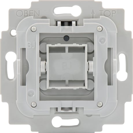
Product Image


1 - Parameter 1
Enable/disable central scene notifications for 2x-5x button pressesSize: 1 byte
Default: 1
Minimum: 0
Maximum: 1
Possible values
| From | To | Desription |
|---|---|---|
| 0 | 1 | Setting this parameter to 0 will disable central scene notifications for multiple (2x-5x button presses). |
2 - Parameter 2
Interval of current wattage meter reports in 10 seconds increments.Size: 2 bytes
Default: 3
Minimum: 0
Maximum: 8640
Possible values
| From | To | Desription |
|---|---|---|
| 0 | 0 | Disable unsolicited meter reports of current wattage. |
| 3 | 8640 | Interval of unsolicited reports in 10s increments (30 seconds - 1 day) |
3 - Parameter 3
Interval of active energy meter reports in minutes.Size: 2 bytes
Default: 60
Minimum: 0
Maximum: 30240
Possible values
| From | To | Desription |
|---|---|---|
| 0 | 0 | Disable unsolicited meter reports of active energy. |
| 10 | 30240 | Interval of unsolicited reports in minutes (10 minutes - 3 weeks) |
4 - Parameter 4
Operations mode for push buttons controlling the output.Size: 1 byte
Default: 0
Minimum: 0
Maximum: 1
Possible values
| From | To | Desription |
|---|---|---|
| 0 | 0 | In this mode the top button will turn the output on, while the bottom button will turn the output off. |
| 1 | 1 | In this mode any button press will toggle the output - when on it will be turned off, when off it will be turned on. |
5 - Parameter 5
Configuration of switch type connected to extension input S.Size: 1 byte
Default: 0
Minimum: 0
Maximum: 1
Possible values
| From | To | Desription |
|---|---|---|
| 0 | 0 | Use this value if a toggle switch is connected to extension input S. |
| 1 | 1 | Use this value if a push button switch is connected to extension input S. |
6 - Parameter 6
Central Scene mapping of extension input S.Size: 1 byte
Default: 1
Minimum: 1
Maximum: 3
Possible values
| From | To | Desription |
|---|---|---|
| 1 | 1 | Multiple button presses (2x-5x) on extension input S will trigger events of central scene 1. |
| 2 | 2 | Multiple button presses (2x-5x) on extension input S will trigger events of central scene 2. |
| 3 | 3 | Multiple button presses (2x-5x) on extension input S will trigger events of central scene 3 - an additional central scene exclusive to extension input S. |
1. Install the TechniSat Single-Switch. 2. After checking the correct installation, re-enable electrical power at the main fuse or circuit breaker. 3. Start the Z-Wave device add mode on your Z-Wave gateway, according to the gateway‘s manual. 4. Press position T1 3x within 1 second. 5. The red status LED is on while the device is added to the Z-Wave network. 6. The green LED is on for 5 seconds after successfully adding the device.
1. Start the Z-Wave device remove mode on your Z-Wave gateway, according to the gateway‘s manual. 2. Press and hold position T1 for more than 10 seconds. 3. The red status LED is on while the device is removed from the Z-Wave network. 4. The green LED is on for 5 seconds after successfully removing the device.
Use this procedure only when the network primary controller is missing or otherwise inoperable. 1. Press and hold position T2 for more than 20 seconds. 2. The LED will alternately flash red and green for 5 seconds after a successful reset.
The Z-Wave QR-Code is located on the back of the product.
| Type | Value(s) |
|---|
| Group | Type |
|---|---|
| Power Management |
|
| Meter type |
|---|
| Electric Meter Consumption |