Aeotec
Recessed Door Sensor 7
ZW187-C
Notification Sensor
HW: 187 FW: 1.02
ZGM130
7.11.00
0x0371 (881)
0x0002 (2)
0x00BB (187)
ZC12-19110018
2019-10-31 17:37:33.659153
N/A
Enhanced 232 Slave
Reporting Sleeping Slave
Yes
It can be embedded inside the wooden door or window. When Magnet is away or near, it will send out notification via Group 1 (Lifeline) or control other Z-Wave device directly via Group 2 .
1. Can be embedded inside the wooden door or window. 2. When Magnet is away or near, it will send out notification via Group 1 (Lifeline) or control other Z-Wave device directly via Group 2. 3. Support SmartStart, which makes inclusion more convenient. 4. Support S2, which makes it more secure and reliable.
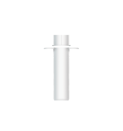
Product Image


1 - Binary Sensor Report
Enable/Disable Binary Sensor Report. Allow for backward compatibility to report Binary if Notification Report cannot be used for status changes.Size: 1 byte
Default: 0
Minimum: 0
Maximum: 1
Possible values
| From | To | Desription |
|---|---|---|
| 0 | 0 | Disable. Sensor Binary Report will NOT be issued via Lifeline when Magnet is away or near. |
| 1 | 1 | Enable. Sensor Binary Report will be issued via Lifeline when Magnet is away or near. |
2 - Sensor Reports
Reverse Sensor Reports (both Sensor Binary Report and Notification Report.)Size: 1 byte
Default: 0
Minimum: 0
Maximum: 1
Possible values
| From | To | Desription |
|---|---|---|
| 0 | 0 | Open Status when Magnet is away, Close Status when magnet is near. |
| 1 | 1 | Close Status when Magnet is away, Open Status when magnet is near. |
3 - Association Group 2 Settings
Configure the Basic Set value. Determine the Basic Set value to control other Z-Wave devices directly when Magnet is away or near.Size: 1 byte
Default: 1
Minimum: 0
Maximum: 6
Possible values
| From | To | Desription |
|---|---|---|
| 0 | 0 | Disable completely. |
| 1 | 1 | Send Basic SET 0xFF when Magnet is away, and send Basic SET 0x00 when Magnet is near. |
| 2 | 2 | Send Basic SET 0x00 when Magnet is away, and send Basic Set 0xFF when Magnet is near. |
| 3 | 3 | Only send Basic SET 0xFF when Magnet is away. |
| 4 | 4 | Only send Basic SET 0x00 when Magnet is near. |
| 5 | 5 | Only send Basic SET 0x00 when Magnet is away. |
| 6 | 6 | Only send Basic SET 0xFF when Magnet is near. |
4 - Application Layer Retry
Configure retry number and wait time. The device supports an application retry mechanism when the application of the device has detected a transmission error when Basic Set, Sensor Binary Report or Notification Report (Access Control) message is sent out but fails to result in an ACK or a Supervision Report.Size: 2 bytes
Default: 0
Minimum: 0
Maximum: 1535
Possible values
| From | To | Desription |
|---|---|---|
| 0 | 1535 | The Byte 1 is used to configure the number of retries. The valid value is 0-5. 0 means disable retry. The Byte 2 is used to configure the wait time between retries. The valid value is 0-255. Unit is 100ms. |
5 - Supervision Report Wait Time
Configure Supervision Report Wait TimeSize: 1 byte
Default: 15
Minimum: 1
Maximum: 50
Possible values
| From | To | Desription |
|---|---|---|
| 1 | 50 | Unit is 100ms. Note: Issuing Basic Set, Sensor Binary Report or Notification Report(Access Control) via association groups uses Supervision encapsulation only if sending commands with S2(or higher security) encapsulation. In other word, this parameter can be configured in any network, but works only in S2 (or higher security) network. |
81 - Led Indicator
Control LED Indicator. Determine whether the LED flash or not when sending Basic Set, Sensor Binary Report, Notification Report (Access Control) or Wake Up Notification.Size: 1 byte
Default: 3
Minimum: 0
Maximum: 3
Possible values
| From | To | Desription |
|---|---|---|
| 0 | 0 | Completely disable LED. |
| 1 | 1 | LED quickly flashes only when sending Basic Set, Sensor Binary Report or Notification Report (Access Control). |
| 2 | 2 | LED activates only when sending Wake Up Notification. |
| 3 | 3 | LED quickly flashes when sending Basic Set, Sensor Binary Report or Notification Report (Access Control), and activates when sending Wake Up Notification. |
90 - Low battery threshold
Configure the low battery threshold. Induce battery report when battery level is less than or equal to threshold. Forward low battery report.Size: 1 byte
Default: 30
Minimum: 10
Maximum: 50
Possible values
| From | To | Desription |
|---|---|---|
| 10 | 50 | 10%-50% |
101 - Timed battery report
Set how often battery is reported in minutes.Size: 2 bytes
Default: 70
Minimum: 1
Maximum: 14400
Possible values
| From | To | Desription |
|---|---|---|
| 1 | 14400 | Set how often battery is reported in minutes. |
1. Press the sensor latch with a slotting screwdriver to remove the lid of the sensor. 2. Squeeze the sides of the sensor casing to alleviate pressure on the chipboard; slide the chipboard out. 3. Remove the Pull Tab to engage the pre-installed battery. The sensor’s LED will fade the color red in and out for a few seconds to indicate that it’s powered on. 4. Set your gateway into its 'add device' mode. Refer to its manual if you are unsure of how to perform this step. Then press Recessed Door Sensor 7's Action Button once; its LED will blink. If your gateway supports S2 security, and you want your device to use this higher level of security, please enter the first 5 digits of the DSK into the gateway's interface when prompted. Refer to the gateway's manual if you are unsure how to perform this step. Do not lose the DSK or remove it from the product or package. 5. When Recessed Door Sensor 7 successfully joins your Z-Wave network its LED will turn solid red for 10 minutes and then off. If fails, its LED turns slow fade-in fade-out red color. Repeat the above steps and please contact us for further support if needed. 6. Squeeze the sides of the sensor casing lightly again and re-insert the chipboard as it was. Re-attach the lid.
1. Set your Z-Wave Controller into its 'Remove Device' mode in order to remove the product from your Z-Wave system. Refer to the Controller's manual if you are unsure of how to perform this step. 2. Make sure the product is powered. 3. Single-click Action Button; LED will become flash red color for 5 seconds, which indicates entering exclusion mode. 4. If the exclusion is successful, LED will change to the default unpaired state which is slow fade-in fade-out red color. 5. Should its LED extinguish without slow fade-in fade-out red color, it indicates the exclusion is unsuccessful. Contact us for further support if needed.
When re-power on, Wake Up Notification will be issued, and the Wake Up destination is according to the Wake Up Interval Set. The Wake Up period starts when the node issues a Wake Up Notification and it ends either 10 seconds after the last received/transmitted frame or at the reception of a Wake Up No More Information Command by the Wake Up destination. If press and hold the Action Button for 2s and release the Action Button when the LED becomes slow pulsing Red color, Wake Up Notification will also be issued, and the Wake Up destination is according to the Wake Up Interval Set. It will stay awake for 10 minutes after issuing Wake Up Notification, or goes into sleep immediately if receives Wake Up No More Information.
If the primary controller is missing or inoperable, you may need to reset the device to factory settings. Make sure the product is powered. To complete the reset process manually, press and hold the Action Button for at least 20s, and release the Action Button when LED becomes solid red color, then Factory Reset is performed. Slow fade-in fade-out red LED color indicates the reset operation is successful. Contact us for further support if needed. Note: 1. This procedure should only be used when the primary controller is missing or inoperable. 2. Factory Reset will: (a) Remove the product from Z-Wave network; (b) Delete the Association setting; (c) Restore the configuration settings to the default.
There is no DSK on the product. In Section Used in this guide, there is a picture showing where the QR and PIN are, as well as a Note saying "QR Code used for SmartStart inclusion. DSK Code can be found on packaging. Do not remove or damage them."
| Type | Value(s) |
|---|
| Group | Type |
|---|---|
| Access Control |
|
| Power Management | Power status: Power has been applied |
| System | SW status: System software failure (manufacturer proprietary failure code provided) |