Schlage
Schlage Connect Smart Deadbolt
BE469ZP
Door Lock - Keypad
HW: 3 FW: 3.03:11.00
ZM5101
6.81.02
0x003B (59)
0x0001 (1)
0x0469 (1129)
ZC10-19116792
2019-11-08 15:11:40.632407
N/A
Routing Slave
Listening Sleeping Slave
Yes
The Schlage Connect Smart Deadbolt combines advanced features and compatibility with home automation or security systems, so you can control your lock from anywhere using your smartphone.
The Schlage Connect™ Smart Deadbolt combines advanced features and compatibility with your home automation or security system, allowing you to control your lock from anywhere and freeing you from the hassles of lost keys, getting locked out, or hiding a spare for friends and family. The lock comes preprogrammed with two access codes and can hold up to 30 unique codes for family members and trusted friends. The fingerprint-resistant touchscreen helps access codes stay private, minimizing tell-tale wear that can tip off possible intruders. The Schlage Connect Smart Deadbolt is battery-powered with a low battery warning that gives you weeks of advanced notice before it runs out. With guaranteed fit on standard doors, it’s easy for homeowners to install in minutes with just a screwdriver. The touchscreen continues to work in the event of a power outage, so you don’t have to worry about getting locked out – plus, a back-up key is included with the lock for peace of mind. The Schlage Connect Smart Deadbolt incorporates Z-Wave Plus S2 technology, an enhanced security protocol that features an additional layer of AES encryption of wireless signals. The Z-Wave technology allows you to integrate your exterior door locks with other Z-Wave smart home devices, such as cameras, motion detectors, lights and thermostats, bringing the safety, simplicity and style of Schlage to your smart home.
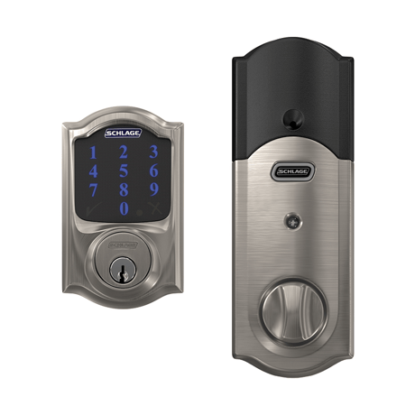
Product Image


3 - Beeper
This configuration setting controls the keypad beeper of the deadbolt allowing the keypad beeper to be turned ON or OFFSize: 1 byte
Default: -1
Minimum: 0
Maximum: 0
Possible values
| From | To | Desription |
|---|---|---|
| -1 | -1 | Enable Beeper |
| 0 | 0 | Disable Beeper |
4 - Vacation Mode
This configuration setting controls the keypad entry of User Codes allowing all User Codes to be turned ON (disable Vacation Mode) or OFF (enable Vacation Mode)Size: 1 byte
Default: 0
Minimum: 0
Maximum: 0
Possible values
| From | To | Desription |
|---|---|---|
| -1 | -1 | Enable Vacation Mode |
| 0 | 0 | Disable Vacation Mode |
5 - Lock and Leave Mode
This configuration setting controls the use of the "Schlage" button on the keypad for single button push for throwing the deadbolt.Size: 1 byte
Default: -1
Minimum: 0
Maximum: 0
Possible values
| From | To | Desription |
|---|---|---|
| -1 | -1 | Enable Lock and Leave Mode |
| 0 | 0 | Disable Lock and Leave Mode |
6 - User Slot Bit Field
This configuration setting indicates the occupied slots (from 1 to 30) that contain User Codes that will activate the deadbolt when entered on the keypad.Size: 4 bytes
Default: 0
Minimum: 0
Maximum: 0
Possible values
| From | To | Desription |
|---|---|---|
| 0 | -1 | User Slot Bit Field |
7 - Lock Specific Alarm Mode
This configuration setting indicates the Mode of the built-in alarm function of the lock.Size: 1 byte
Default: 0
Minimum: 0
Maximum: 0
Possible values
| From | To | Desription |
|---|---|---|
| 0 | 3 | Lock Specific Alarm Mode |
8 - Lock Specific Alarm Alert Sensitivity
This configuration setting indicates the sensitivity setting of the Alert function of the built-in alarm.Size: 1 byte
Default: 3
Minimum: 0
Maximum: 0
Possible values
| From | To | Desription |
|---|---|---|
| 1 | 5 | Alarm Alert Sensitivity |
9 - Lock Specific Alarm Tamper Sensitivity
This configuration setting indicates the sensitivity setting of the Tamper function of the built-in alarm.Size: 1 byte
Default: 3
Minimum: 0
Maximum: 0
Possible values
| From | To | Desription |
|---|---|---|
| 1 | 5 | Alarm Tamper Sensitivity |
10 - Lock Specific Alarm Kick Sensitivity
This configuration setting indicates the sensitivity setting of the Forced Entry function of the built-in alarm.Size: 1 byte
Default: 3
Minimum: 0
Maximum: 0
Possible values
| From | To | Desription |
|---|---|---|
| 1 | 5 | Alarm Forced Entry Sensitivity |
11 - Lock Specific Alarm Disable Local Controls
This configuration setting controls the ability to ENABLE or DISABLE local control of the built-in alarm function.Size: 1 byte
Default: -1
Minimum: 0
Maximum: 0
Possible values
| From | To | Desription |
|---|---|---|
| -1 | -1 | Alarm Enable Local Controls |
| 0 | 0 | Alarm Disable Local Controls |
12 - Get Electronic Transition Count
This configuration setting indicates the number of transitions from locked to unlocked or unlocked to locked state via electronic activation.Size: 4 bytes
Default: 0
Minimum: 0
Maximum: 0
Possible values
| From | To | Desription |
|---|---|---|
| 0 | -1 | Electronic State Change Count |
13 - Get Mechanical Transition Count
This configuration setting indicates the number of transitions from locked to unlocked or unlocked to locked state via mechanical activation.Size: 4 bytes
Default: 0
Minimum: 0
Maximum: 0
Possible values
| From | To | Desription |
|---|---|---|
| 0 | -1 | Mechanical State Change Count |
14 - Get Electronic Failed Count
This configuration setting indicates the number of failed electronic activation attempts for this lock.Size: 4 bytes
Default: 0
Minimum: 0
Maximum: 0
Possible values
| From | To | Desription |
|---|---|---|
| 0 | -1 | Failed Electronic Activation Count |
15 - Auto Lock
This configuration setting controls the lock feature that automatically throws the deadbolt 30 seconds after a valid User Code has been entered at the keypad.Size: 1 byte
Default: 0
Minimum: 0
Maximum: 0
Possible values
| From | To | Desription |
|---|---|---|
| -1 | -1 | Enable Auto Lock |
| 0 | 0 | Disable Auto Lock |
16 - User Code PIN Length
This configuration setting controls the length of all User Codes stored in the lock. The values are 4 to 8 with default set to 4.Size: 1 byte
Default: 4
Minimum: 0
Maximum: 0
Possible values
| From | To | Desription |
|---|---|---|
| 4 | 8 | User Code PIN Length |
17 - Get Electrical High Preload Transition Count
This configuration setting indicates the number of transitions from locked to unlocked or unlocked to locked state via electronic activation that indicated a high preload on the deadbolt. This value is a subset of Parameter 12.Size: 4 bytes
Default: 0
Minimum: 0
Maximum: 0
Possible values
| From | To | Desription |
|---|---|---|
| 0 | -1 | Electronic State Change Count with High Preload |
18 - Get Bootloader Version
This configuration setting returns the version number of the bootloader in the lock.Size: 1 byte
Default: 0
Minimum: 0
Maximum: 0
Possible values
| From | To | Desription |
|---|---|---|
| 0 | -1 | Get Bootloader Version |
One-button Add lock to Z-Wave Network (Inclusion) 1. Place your home automation system or panel into the “Add” or Inclusion Mode (Refer to the respective documentation for that specific home automation system or panel device for details). 2. Remove the battery cover of the deadbolt. 3. Press then release the button on the PCB. 4. An LED will flash amber indicating the “Add” or Inclusion process is in progress. • If the Security Scheme is Security 2 (S2), verify the DSK of the lock at the Z-Wave Controller. The PIN Code portion of the Z-Wave DSK will be needed. 5. When a green LED turns ON, the “Add” or Inclusion has completed successfully. 6. If a red LED turns ON, try repeating steps 1-3 Interactive Instruction for Add https://instructions.allegion.com/instr/86/2543
One-button Remove lock from Z-Wave Network (Exclusion) 1. Place your home automation system or panel into the “Remove” or Exclusion Mode (Refer to the respective documentation for that specific home automation system or panel device for details). 2. Remove the battery cover of the deadbolt. 3. Press then release the button on the PCB. 4. An LED will flash amber indicating the “Remove” or Exclusion process is in progress. 5. When a green LED flashes 3 times, the “Remove” or Exclusion process is completed successfully. 6. If a red LED turns ON, try repeating steps 1-3 Interactive Instruction for Remove https://instructions.allegion.com/instr/86/2581
Not applicable. The lock is a FLIRS device.
Steps for One-button Factory Default Reset 1. Remove the battery cover of the deadbolt 2. Press and hold the button on the PCB for 7 (seven) seconds. While holding the button pressed, after 1 sec LED will be lit for 2 sec. and turn OFF; continue to press and hold the button until the LED will be lit again and release the button. 3. The LED will blink red three times and the green check on the touchscreen will blink if the Factory Default Reset is successful. 4. To check that the lock was reset, press the Schlage Button and enter one of the Default User Codes. If the reset was successful, the Default User Codes will unlock the deadbolt. NOTE: Please use this procedure only when the network primary controller is missing or otherwise inoperable.
The DSK is located on the back side of the inside escutcheon
| Type | Value(s) |
|---|
| Group | Type |
|---|---|
| Access Control | (Refer to parameters): State idle |
| Power Management | (Refer to parameters): State idle |
| System | (Refer to parameters): State idle |