B.One
B.One Dual Relay
B1DR01-ZW-IN
On/Off Power Switch
HW: 140 FW: 12.00:01.02
ZM5101
6.51.09
0x0311 (785)
0x0903 (2307)
0x008C (140)
ZC10-19116801
2019-11-22 16:32:57.820196
N/A
Enhanced 232 Slave
Always On Slave
Z-Wave Dual Relay Switch
Dual Relay is a Z-Wave power binary switch device based on Z-Wave enhanced 232 slave library V6.51.10. You can use it to control your home light or bulbs on/off. It can connect to 2 external manual switches to control the load ON/OFF independently. Its surface has a pin socket, which can be used for connecting to the touch panel, so you can also use the touch panel to control the Dual Relay Switch. It can also be included and operated in any Z-Wave network with other Z-Wave certified devices from other manufacturers and/or other applications. All non-battery operated nodes within the network will act as repeaters regardless of vendor to increase reliability of the network. It is a security Z-Wave plus device, so a security enabled controller is needed for take full advantage of all functionally for the Relay Switch. It also supports the Over The Air (OTA) feature for the product’s firmware upgrade. As soon as Dual Relay is removed from a Z-Wave network it will be restored into default factory setting.
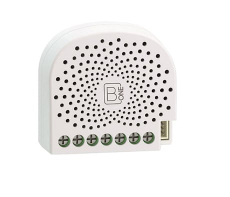
Product Image


4 - Overheat protection.
Output Load will be turned off automatically after 30 seconds and if the temperature of product inside exceeds 100 ℃.Size: 1 byte
Default: 0
Minimum: 0
Maximum: 0
Possible values
| From | To | Desription |
|---|---|---|
| 0 | 0 | Disable |
| 1 | 1 | Enable |
20 - Configure the output status after re-power on it.
Configure the output status after re-power on it.Size: 1 byte
Default: 0
Minimum: 0
Maximum: 0
Possible values
| From | To | Desription |
|---|---|---|
| 0 | 0 | Last status |
| 1 | 1 | Always on |
| 2 | 2 | Always off |
80 - To set which notification would be sent to the associated devices (Group 1)
To set which notification would be sent to the associated devices (Group 1) when the state of Nano Dimmer’s load is changed.Size: 1 byte
Default: 0
Minimum: 0
Maximum: 0
Possible values
| From | To | Desription |
|---|---|---|
| 0 | 0 | Send Nothing |
| 1 | 1 | Send Hail CC |
| 2 | 2 | Send Basic CC report |
| 3 | 3 | Send Hail CC when using the manual switch to change the load state. |
81 - To set which notification would be sent to the associated nodes in association group 3
To set which notification would be sent to the associated nodes in association Group 3 when using the external switch 1 to switch the loads.Size: 1 byte
Default: 1
Minimum: 0
Maximum: 0
Possible values
| From | To | Desription |
|---|---|---|
| 0 | 0 | Send Nothing |
| 1 | 1 | Send Basic Set CC |
82 - To set which notification would be sent to the associated nodes in association group 4
To set which notification would be sent to the associated nodes in association Group 4 when using the external switch 2 to switch the loads.Size: 1 byte
Default: 1
Minimum: 0
Maximum: 0
Possible values
| From | To | Desription |
|---|---|---|
| 0 | 0 | Send Nothing |
| 1 | 1 | Send Basic Set CC |
83 - Configure the state of LED when it is in 3 modes
Configure the state of LED when it is in 3 modes (Energy mode, Momentary indicate mode, Night light mode)Size: 1 byte
Default: 0
Minimum: 0
Maximum: 0
Possible values
| From | To | Desription |
|---|---|---|
| 0 | 0 | Energy mode. The LED will follow the status (on/off). |
| 1 | 1 | Momentary indicate mode. When the state of Switch’s load changed, the LED will follow the status (on/off) of its load, but the LED will turn off after 5 seconds if there is no any switch action. |
| 2 | 2 | Night light mode. The LED will remain ON state. |
84 - Set the ON/OFF time of the LED when it is in Night light mode.
Set the ON/OFF time of the LED when it is in Night light mode.Size: 4 bytes
Default: 301991936
Minimum: 0
Maximum: 0
Possible values
| From | To | Desription |
|---|---|---|
| 0 | 60 | The minute time of OFF |
| 256 | 316 | The hour time of OFF |
| 65536 | 65596 | The minute time of ON |
| 16777216 | 16777276 | The hour time of ON |
86 - Set appointment 1
Set the ON time of output load.Size: 4 bytes
Default: 8327680
Minimum: 0
Maximum: 0
Possible values
| From | To | Desription |
|---|---|---|
| 0 | 60 | The minute value of ON time |
| 256 | 316 | The hour value of ON time |
| 65536 | 65543 | The day value (Mon to Sun) |
| 16777215 | 16777215 | Disable the setting. |
| 16777216 | 16777216 | Enable the setting. |
87 - Set appointment 2
Set the OFF time of output load.Size: 4 bytes
Default: 8327680
Minimum: 0
Maximum: 0
Possible values
| From | To | Desription |
|---|---|---|
| 0 | 60 | The minute value of ON time |
| 256 | 316 | The hour value of ON time |
| 65536 | 65543 | The day value (Mon to Sun) |
| 16777215 | 16777215 | Disable the setting. |
| 16777216 | 16777216 | Enable the setting. |
120 - Configure the external switch mode for S1.
Configure the external switch mode for S1.Size: 1 byte
Default: 0
Minimum: 0
Maximum: 0
Possible values
| From | To | Desription |
|---|---|---|
| 0 | 0 | Enter automatic identification mode |
| 1 | 1 | 2-state switch mode |
| 2 | 2 | 3 way switch mode |
| 3 | 3 | Momentary push button mode |
121 - Configure the external switch mode for S2.
Configure the external switch mode for S2.Size: 1 byte
Default: 0
Minimum: 0
Maximum: 0
Possible values
| From | To | Desription |
|---|---|---|
| 0 | 0 | Enter automatic identification mode |
| 1 | 1 | 2-state switch mode |
| 2 | 2 | 3 way switch mode |
| 3 | 3 | Momentary push button mode |
122 - Set the control destination for external switch S1
Set the control destination for external switch S1Size: 1 byte
Default: 3
Minimum: 1
Maximum: 3
Possible values
| From | To | Desription |
|---|---|---|
| 1 | 1 | control the output loads of itself. |
| 2 | 2 | control the other nodes |
| 3 | 3 | control the output loads of itself and other nodes. |
123 - Set the control destination for external switch S2
Set the control destination for external switch S2Size: 1 byte
Default: 3
Minimum: 1
Maximum: 3
Possible values
| From | To | Desription |
|---|---|---|
| 1 | 1 | control the output loads of itself. |
| 2 | 2 | control the other nodes. |
| 3 | 3 | control the output loads of itself and other nodes. |
252 - Lock/unlock configuration parameters
Lock/unlock configuration parameters.Size: 1 byte
Default: 0
Minimum: 0
Maximum: 0
Possible values
| From | To | Desription |
|---|---|---|
| 0 | 0 | Unlock |
| 1 | 1 | Lock |
255 - Reset the Dual Relay Switch
Reset the Dual Relay Switch to factory default.Size: 4 bytes
Default: 0
Minimum: 0
Maximum: 0
Possible values
| From | To | Desription |
|---|---|---|
| 0 | 0 | Reset all configuration parameters to factory default setting |
| 1431655765 | 1431655765 | Reset to factory default setting and removed from the Z-Wave network |
Turn the primary controller of Z-Wave network into inclusion mode, short press the product’s Action button that you can find on the product's housing.
Turn the primary controller of Z-Wave network into exclusion mode, short press the product’s Action button that you can find on the product's housing.
Press and hold the Action button that you can find on the product's housing for 20 seconds and then release. This procedure should only be used when the primary controller is inoperable.
Support ""Over the Air Firmware Updating"" and “Z-Wave Security”.
| Type | Value(s) |
|---|
| Group | Type |
|---|---|
| Heat Alarm |
|