Zooz
RGBW DIMMER ZEN31
ZEN31
Multilevel Switch - Color Tunable Multilevel
HW: 2 FW: 5.00:05.00:01.00
ZM5101
6.81.03
0x027A (634)
0x0902 (2306)
0x2000 (8192)
ZC10-19126818
2019-12-09 18:21:08.244386
N/A
Enhanced 232 Slave
Always On Slave
Use this tiny RGBW dimmer to add Z-Wave to your existing DC lighting like color LED strips, under cabinet DC lighting, and more.
FEATURES: - Manual or Z-Wave on/off, brightness, and RGBW color control - Perfect for programming your existing RGBW LED strip - Energy monitoring in live mode and over time - Double tap to full brightness feature + optional scene control - Remembers and restores on/off status after power failure - Built-in Z-Wave Plus signal repeater to extend network range - S2 security protocol and AES-128 bank-grade encryption SPECIFICATIONS: - Model Number: ZEN31 - Z-Wave Signal Frequency: 908.42 MHz - Power: 12 / 24 V DC (Do NOT connect to 120 V AC high-voltage power!) - Maximum Load: 10 A total between all channels (6 A per channel max); 120 W total when powered by 12 V DC / 240 W total when powered by 24 V DC - Range: Up to 100 feet line of sight - Operating Temperature: 32-104° F (0-40° C) - Installation and Use: Indoor only - Dimensions: 1.67” x 1.5” x 0.69”
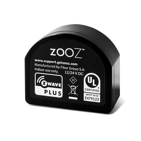
Product Image


1 - On Off Status After Power Failure
Set the on off status for the RGBW Dimmer after power failure.Size: 1 byte
Default: 0
Minimum: 0
Maximum: 2
Possible values
| From | To | Desription |
|---|---|---|
| 0 | 0 | forced to OFF (regardless of state prior to power outage) |
| 1 | 1 | remem-bers and restores on/off status after power failure |
| 2 | 2 | forced to ON (regard-less of state prior to power outage) |
20 - Switch / Input Type for IN1
Choose the input / switch type you want to connect to the IN1 terminal.Size: 1 byte
Default: 2
Minimum: 0
Maximum: 4
Possible values
| From | To | Desription |
|---|---|---|
| 0 | 0 | analog sensor with no pull-up |
| 1 | 1 | analog sensor with pull-up |
| 2 | 2 | momentary switch (default) |
| 3 | 3 | toggle switch (state changes whenever the switch is toggled) |
| 4 | 4 | toggle switch (light on when the switch is toggled up, light off when the switch is toggled down) |
21 - Switch / Input Type for IN2
Choose the input / switch type you want to connect to the IN2 terminal.Size: 1 byte
Default: 2
Minimum: 0
Maximum: 4
Possible values
| From | To | Desription |
|---|---|---|
| 0 | 0 | analog sensor with no pull-up |
| 1 | 1 | analog sensor with pull-up |
| 2 | 2 | momentary switch (default) |
| 3 | 3 | toggle switch (state changes whenever the switch is toggled) |
| 4 | 4 | toggle switch (light on when the switch is toggled up, light off when the switch is toggled down) |
22 - Switch / Input Type for IN3
Choose the input / switch type you want to connect to the IN3 terminal.Size: 1 byte
Default: 2
Minimum: 0
Maximum: 4
Possible values
| From | To | Desription |
|---|---|---|
| 0 | 0 | analog sensor with no pull-up |
| 1 | 1 | analog sensor with pull-up |
| 2 | 2 | momentary switch (default) |
| 3 | 3 | toggle switch (state changes whenever the switch is toggled) |
| 4 | 4 | toggle switch (light on when the switch is toggled up, light off when the switch is toggled down) |
23 - Switch / Input Type for IN4
Choose the input / switch type you want to connect to the IN4 terminal.Size: 1 byte
Default: 2
Minimum: 0
Maximum: 4
Possible values
| From | To | Desription |
|---|---|---|
| 0 | 0 | analog sensor with no pull-up |
| 1 | 1 | analog sensor with pull-up |
| 2 | 2 | momentary switch (default) |
| 3 | 3 | toggle switch (state changes whenever the switch is toggled) |
| 4 | 4 | toggle switch (light on when the switch is toggled up, light off when the switch is toggled down) |
40 - Scene Control for IN1
Assign scene activation trigger for IN1 terminal. Enter the sum of values to enable more than 1 trigger.Size: 1 byte
Default: 15
Minimum: 0
Maximum: 15
Possible values
| From | To | Desription |
|---|---|---|
| 0 | 0 | scene control disabled |
| 1 | 1 | click / toggle the connected switch once to trigger a scene |
| 2 | 2 | click / toggle the connected switch twice to trigger a scene |
| 4 | 4 | click / toggle the connected switch 3 times to trigger a scene |
| 8 | 8 | hold and release the connected momentary switch to trigger a scene |
41 - Scene Control for IN2
Assign scene activation trigger for IN2 terminal. Enter the sum of values to enable more than 1 trigger.Size: 1 byte
Default: 15
Minimum: 0
Maximum: 15
Possible values
| From | To | Desription |
|---|---|---|
| 0 | 0 | scene control disabled |
| 1 | 1 | click / toggle the connected switch once to trigger a scene |
| 2 | 2 | click / toggle the connected switch twice to trigger a scene |
| 4 | 4 | click / toggle the connected switch 3 times to trigger a scene |
| 8 | 8 | hold and release the connected momentary switch to trigger a scene |
42 - Scene Control for IN3
Assign scene activation trigger for IN3 terminal. Enter the sum of values to enable more than 1 trigger.Size: 1 byte
Default: 15
Minimum: 0
Maximum: 15
Possible values
| From | To | Desription |
|---|---|---|
| 0 | 0 | scene control disabled |
| 1 | 1 | click / toggle the connected switch once to trigger a scene |
| 2 | 2 | click / toggle the connected switch twice to trigger a scene |
| 4 | 4 | click / toggle the connected switch 3 times to trigger a scene |
| 8 | 8 | hold and release the connected momentary switch to trigger a scene |
43 - Scene Control for IN4
Assign scene activation trigger for IN4 terminal. Enter the sum of values to enable more than 1 trigger.Size: 1 byte
Default: 15
Minimum: 0
Maximum: 15
Possible values
| From | To | Desription |
|---|---|---|
| 0 | 0 | scene control disabled |
| 1 | 1 | click / toggle the connected switch once to trigger a scene |
| 2 | 2 | click / toggle the connected switch twice to trigger a scene |
| 4 | 4 | click / toggle the connected switch 3 times to trigger a scene |
| 8 | 8 | hold and release the connected momentary switch to trigger a scene |
62 - Power Report Frequency
Choose how often you want your RGBW Dimmer to report power consumption (W) to your controller. The number entered as value corresponds to the number of seconds. So if 3600 is entered by default, the RGBW Dimmer will report power consumption every hour. Power reports are sent in at least 30-second intervals.Size: 2 bytes
Default: 3600
Minimum: 0
Maximum: 32400
Possible values
| From | To | Desription |
|---|---|---|
| 0 | 0 | disabled (it will not report power consumption based on the fre- quency setting) |
| 30 | 32400 | seconds |
63 - Analog Sensor Voltage Reporting / Trigger Threshold
Choose how you want your RGBW Dimmer to report voltage changes from the connected analog sensors and trigger status change on the output. The number entered as value corresponds to decimal values in voltage change. So if 5 is entered by default, the RGBW Dimmer will report any change in voltage of the connected sensor over 0.5 V. This setting is only in effect if at least one of Parameters 20 – 23 is set to value 0 or 1 (input is set to analog sensor mode).Size: 2 bytes
Default: 5
Minimum: 0
Maximum: 100
Possible values
| From | To | Desription |
|---|---|---|
| 0 | 0 | disabled (it will not report voltage based on value change) |
| 1 | 100 | 0.1 – 10 V |
64 - Analog Sensor Report Frequency
Choose how often you want your RGBW Dimmer to report voltage changes from the connected analog sensors to your hub. The number entered as value corresponds to the number of seconds. So if 3600 is entered as value, the RGBW Dimmer will report voltage from connected analog sensors every hour (independent of the threshold set in parameter 63). Voltage reports are sent in at least 30-second intervals. This setting is only in effect if at least one of Parameters 20 – 23 is set to value 0 or 1 (input is set to analog sensor mode).Size: 2 bytes
Default: 0
Minimum: 0
Maximum: 32400
Possible values
| From | To | Desription |
|---|---|---|
| 0 | 0 | disabled (it will not report voltage based on the frequency setting) |
| 30 | 32400 | seconds |
65 - Energy Report Threshold
Choose how you want your RGBW Dimmer to report energy use (kWh) to your hub. The number entered as value corresponds to decimal values in energy usage change. So if 10 is entered by default, the RGBW Dimmer will report any change in energy use over 0.1 kWh. Energy reports are sent in at least 30-second intervals.Size: 2 bytes
Default: 10
Minimum: 0
Maximum: 500
Possible values
| From | To | Desription |
|---|---|---|
| 0 | 0 | disabled (it will not report energy use based on value change) |
| 1 | 500 | 0.01 - 5 kWh |
66 - Energy Report Frequency
Choose how often you want your RGBW Dimmer to report energy (kWh) to your controller. The number entered as value corresponds to the number of seconds. So if 3600 is entered by default, the RGBW Dimmer will report energy use every hour (independent of the threshold set in parameter 65). Energy reports are sent in at least 30-second intervals.Size: 2 bytes
Default: 3600
Minimum: 0
Maximum: 32400
Possible values
| From | To | Desription |
|---|---|---|
| 0 | 0 | disabled (it will not report energy use based on the frequency setting) |
| 30 | 32400 | seconds |
150 - RGBW / HSB Wall Switch Mode
Choose how switches connected to the input terminals control your LED strip. In the default RGBW mode, each switch connected to each input terminal controls the RGBW channels separately (so IN1 for red, IN2 for green, etc) with a single click for ON/OFF, double click to full brightness, and press-and-hold to dim (momentary switches only). In the HSB mode, IN1 controls hue, IN2 – saturation, IN3 – brightness, IN4 – white with single click for last set value or value 0, double click to max value, and press-and-hold to set custom value.Size: 1 byte
Default: 0
Minimum: 0
Maximum: 1
Possible values
| From | To | Desription |
|---|---|---|
| 0 | 0 | RGBW mode (default) |
| 1 | 1 | HSB mode |
151 - Physical Ramp Rate
Adjust the ramp rate for your RGBW dimmer (fade-in / fade-out effect for on / off operation). Values correspond to the number of seconds it take for the dimmer to reach full brightness or turn off when operated from the connected wall switch.Size: 2 bytes
Default: 3
Minimum: 0
Maximum: 254
Possible values
| From | To | Desription |
|---|---|---|
| 0 | 0 | instant on/off |
| 1 | 127 | seconds |
| 128 | 254 | 1 - 127 minutes |
152 - Z-Wave Ramp Rate
Adjust the ramp rate for your RGBW dimmer when operated remotely from the Z-Wave hub.Size: 2 bytes
Default: 3
Minimum: 0
Maximum: 254
Possible values
| From | To | Desription |
|---|---|---|
| 0 | 0 | instant on/off |
| 1 | 127 | seconds |
| 128 | 254 | 1 - 127 minutes |
154 - Single Click ON Trigger for Associated Devices
Set the status or brightness level triggering other associated devices in your network if the dimmer is turned ON with a single click. Each of the 4 available bytes refers to one channel, starting with IN1 and ending with IN4. This setting applies to basic set and switch multilevel commands sent to associated devices in the appropriate association group.Size: 4 bytes
Default: 255
Minimum: 0
Maximum: 255
Possible values
| From | To | Desription |
|---|---|---|
| 0 | 99 | custom brightness level |
| 255 | 255 | ON |
155 - Single Click OFF Trigger for Associated Devices
Set the status or brightness level triggering other associated devices in your network if the dimmer is turned OFF with a single click. Each of the 4 available bytes refers to one channel, starting with IN1 and ending with IN4. This setting applies to basic set and switch multilevel commands sent to associated devices in the appropriate association group.Size: 4 bytes
Default: 0
Minimum: 0
Maximum: 255
Possible values
| From | To | Desription |
|---|---|---|
| 0 | 99 | custom brightness level |
| 255 | 255 | ON |
156 - Double Click ON Trigger for Associated Devices
Set the status or brightness level triggering other associated devices in your network if the dimmer is turned ON with a double click. Each of the 4 available bytes refers to one channel, starting with IN1 and ending with IN4. This setting applies to basic set and switch multilevel commands sent to associated devices in the appropriate association group.Size: 4 bytes
Default: 99
Minimum: 0
Maximum: 255
Possible values
| From | To | Desription |
|---|---|---|
| 0 | 99 | custom brightness level |
| 255 | 255 | ON |
157 - Preset Programs
Enable one of the preset animated color programs to set the mood with a click.Size: 1 byte
Default: 0
Minimum: 0
Maximum: 10
Possible values
| From | To | Desription |
|---|---|---|
| 0 | 0 | preset programs disabled (default) |
| 6 | 6 | fireplace |
| 7 | 7 | storm |
| 8 | 8 | rainbow |
| 9 | 9 | polar lights |
| 10 | 10 | police (strobing red, white, and blue) |
1. Add device to your hub: Initiate inclusion (pairing) in the app (or web Interface). Not sure how? [email protected] If you’re using Smart Start on an S2 hub, it may ask you to enter the DSK key printed on the back cover sticker or scan the QR code next to it to complete secure inclusion. 2. Activate the dimmer Make sure the RGBW Dimmer is powered up. Click the Z-Wave button 3 times quickly to include the device. The LED will blink yellow to indicate communi-cation with the hub. It will blink green (for non-secure, S0, or S2 unauthentica-ted inclusion) or magenta (for S2 authenticated) once the device is successfu-lly included to your network. It will blink red if inclusion is not successful.
1. Bring your Z-Wave gateway (hub) close to the RGBW Dimmer if possible 2. Put the Z-Wave hub into exclusion mode (not sure how to do that? [email protected]) 3. Click the Z-Wave button on the device 3 times quickly 4. Your hub will confirm exclusion, the LED indicator on the RGBW Dimmer will light up in red, and the device will disappear from your controller's device list
If your primary controller is missing or inoperable, you may need to reset the device to factory settings. To complete the reset process manually, press and hold the Z-Wave button to enter reset mode. Release the button when the LED indicator glows yellow. Then quickly click the Z-Wave button again to confirm factory reset. Wait a few seconds until the device resets and restarts - the LED indicator will light up in red when it’s ready. NOTE: All previously recorded activity and custom settings will be erased from the device’s memory.
If you’re using Smart Start on an S2 hub, it may ask you to enter the DSK key printed on the back cover sticker or scan the QR code next to it to complete secure inclusion.
| Type | Value(s) |
|---|
| Group | Type |
|---|---|
| Power Management | Over-current status: Over-current detected |
| System | HW status: System hardware failure (manufacturer proprietary failure code provided) |
| Sensor type |
|---|
| Power |
| Voltage |
| Meter type |
|---|
| Electric Meter Consumption |