Q-light
Z-Wave Puck
1414140.0
Light Dimmer Switch
HW: 255 FW: 4.03
ZM5202
6.81.06
0x0433 (1075)
0x0003 (3)
0x0005 (5)
ZC10-20016847
2020-01-17 16:44:55.163251
N/A
Enhanced 232 Slave
Always On Slave
Z-Wave Puck 2-180W LED load 0-100% dimming range
Z-Wave Puck dimmer by Q-light is a micro size in wall dimmer. Features: - 0-100% dimming range - 2-180W LED load - Compatible with any Z-Wave or Z-Wave Plus Controller - There is memorized function at power off - OverLoad protection - Soft start function - SmartStart - Works with various types of switches – on/off, momentary, roller-blind, and etc - This device is a security enable Z-Wave Plus product that is able to use encrypted Z-Wave Plus messages to communicate to other security enable Z-Wave Plus products.
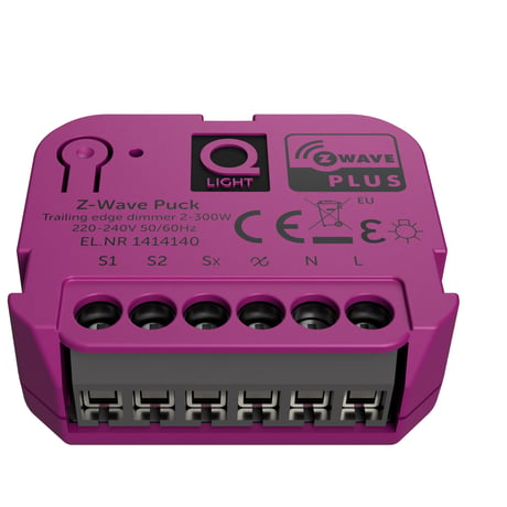
Product Image
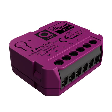
Side view
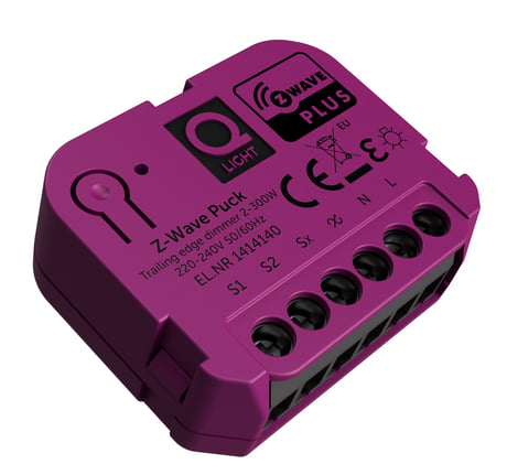
Front view
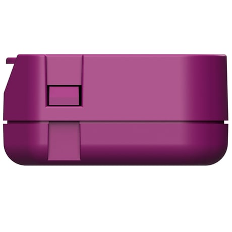
Angled view left
Front angled view
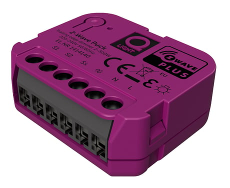
Z Wave Puck Dimmer


1 - Minimum brightness level
This parameter refers to the minimum brightness that the dimmer can achieve.But not exceed the Maximum brightness levelSize: 1 byte
Default: 15
Minimum: 1
Maximum: 98
Possible values
| From | To | Desription |
|---|---|---|
| 10 | 15 | The minimum brightness that the dimmer can achieve is 15. |
2 - Maximum brightness level
This parameter refers to the maximum brightness that the dimmer can achieveSize: 1 byte
Default: 99
Minimum: 2
Maximum: 99
Possible values
| From | To | Desription |
|---|---|---|
| 90 | 98 | The maximum brightness that the dimmer can achieve is 98. |
3 - Automatic control - dimming step size
This parameter defines the percentage value of dimming step during the automatic control.Size: 1 byte
Default: 1
Minimum: 1
Maximum: 99
Possible values
| From | To | Desription |
|---|---|---|
| 1 | 2 | The percentage value of dimming step during the automatic control is 2. |
4 - Automatic control - time of a dimming step
This parameter defines the time of single dimming step set in parameter 3 during the automatic control. Available settings:1-255(10ms-2.55s,in 10ms steps). Default value:1(10ms)Size: 2 bytes
Default: 1
Minimum: 1
Maximum: 255
Possible values
| From | To | Desription |
|---|---|---|
| 1 | 2 | The time of single dimming step set in parameter 3 during the automatic control is 20ms. |
5 - Manual control - dimming step size
This parameter defines the percentage value of dimming step during the manual control.Size: 1 byte
Default: 1
Minimum: 1
Maximum: 99
Possible values
| From | To | Desription |
|---|---|---|
| 1 | 2 | The percentage value of dimming step during the manual control is 2. |
6 - Manual control - time of a dimming step
This parameter defines the time of single dimming step set in parameter 5 during the manual control. Available settings:1-255(10ms-2.55s,in 10ms steps). Default value:5(50ms)Size: 2 bytes
Default: 5
Minimum: 1
Maximum: 255
Possible values
| From | To | Desription |
|---|---|---|
| 3 | 5 | The time of single dimming step set in parameter 5 during the manual control is 50ms. |
7 - Memory function after power failure
If this parameter is set to 1,the Device will restore its brightness before power failure.Size: 1 byte
Default: 1
Minimum: 0
Maximum: 1
Possible values
| From | To | Desription |
|---|---|---|
| 1 | 0 | The Device will not restore its brightness before power failure. |
8 - Switch type
Configure this parameter according to the type of switch the device is connected to. Available settings: 0 – momentary (Push) switch 1 – ON/OFF switch 2– roller blind switch-two switchs operate the device(S1 to brighter,S2 to dimSize: 1 byte
Default: 0
Minimum: 0
Maximum: 2
Possible values
| From | To | Desription |
|---|---|---|
| 0 | 1 | If the device is connected to ON/OFF switch,This parameter must set to 1. |
9 - Switch functionality of S1 and S2
If this parameter is set to 1, the device performs S2 function when S1 is pressed, and S1 function when S2 is pressed.Size: 1 byte
Default: 0
Minimum: 0
Maximum: 1
Possible values
| From | To | Desription |
|---|---|---|
| 0 | 1 | The device performs S2 function when S1 is pressed, and S1 function when S2 is pressed. |
10 - S1 Scene ID set
S1 Scene ID is set by this configuration. Note: The actual action of each SCENE ID are set by SCENE_ACTUATOR_CONF(0x26) command.Size: 2 bytes
Default: 1
Minimum: 1
Maximum: 255
Possible values
| From | To | Desription |
|---|---|---|
| 1 | 3 | When you press S1 five times,the light is dimmed to the brightness set in Scene ID 3 . |
11 - S2 Scene ID set
S2 Scene ID is set by this configuration. Note: The actual action of each SCENE ID are set by SCENE_ACTUATOR_CONF(0x26) command.Size: 2 bytes
Default: 2
Minimum: 1
Maximum: 255
Possible values
| From | To | Desription |
|---|---|---|
| 2 | 5 | When you press S1 five times,the light is dimmed to the brightness set in Scene ID 5. |
12 - Timer functionality (auto - off)
This parameter allows to automatically switch off the device after specified time from switching on the light source. It may be useful when the D300IZ-Q is installed in the stairway. Available settings: 0 - Function disabled 1-32767 - time to turn off measured in seconds (1s-9.1h)Size: 2 bytes
Default: 0
Minimum: 0
Maximum: 32767
Possible values
| From | To | Desription |
|---|---|---|
| 0 | 20 | The device will automatically switch off after 20s from switching on the light source. |
Classic Learn Mode: 1. Place the Z-Wave Puck within the direct range of your Z-Wave controller. 2. Identify switch S1/S2 (turns the light on) or the Internal button (located on the device’s housing). 3. Set the main controller in (security/non-security) add mode (see the controller’s manual). 4. Quickly, three times press switch S1 / S2 or Internal button. 5. Wait for the adding process to end. 6. Successful adding will be confirmed by the Z-Wave controller’s message.
Removing (Exclusion): Allowing to remove the Z-Wave device from existing Z-Wave network. 1. Place the Z-Wave Puck within the direct range of your Z-Wave controller. 2. Identify switch S1/S2 (turns the light on) or the Internal button (located on the device’s housing). 3. Set the main controller in (security/non-security) add mode (see the controller’s manual). 4. Quickly, three times press switch S1 / S2 or Internal button. 5. Wait for the removing process to end.
Resetting the Z-Wave Puck: 1. Quickly, nine times press switch S1 / S2 or Internal button. 2. Wait for the resetting process to end, which is signaled with the LED indicator blinks 20 times. Device reset status: Turn on the light at maximum brightness. Please use this procedure only when the network primary controller is missing or otherwise inoperable
1.Association - Instructions_ZWavePuck_English_A4,page 2 2.Notification - Instructions_ZWavePuck_English_A4,page 2 3.Advanced parameters - Instructions_ZWavePuck_English_A4,page 2
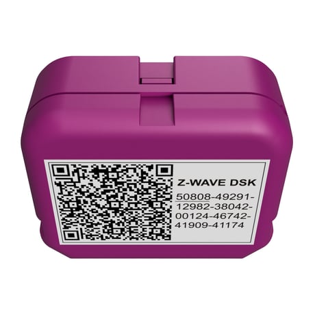
Security 2 DSK is located on the backside of the product See Instructions_ZWavePuck_English_A4,page 1
| Type | Value(s) |
|---|
| Group | Type |
|---|---|
| Heat Alarm | Heat sensor status: Overheat detected |
| Power Management | Over-load status: Over-load detected |