QUBINO
Flush On/Off Thermostat 2
ZMNKID3
Thermostat - HVAC
HW: 1 FW: 10.00:10.00
ZM5202
6.81.03
0x0159 (345)
0x0005 (5)
0x0054 (84)
ZC10-20036879
2020-03-02 15:37:25.311748
N/A
Enhanced 232 Slave
Always On Slave
The Qubino Flush On/Off Thermostat 2 can turn On/OFF the connected electrical device and can measure the power consumption of the connected device. All of that can be done manually or remotely. And: - It supports SmartStart inclusion for quick set up - Works on 110-240 VAC or 24-30 VDC
The Qubino On/Off Thermostat 2 is a wireless heating and hot water controller that also measures the power consumption. It's ideal for wireless control of electric or water-based underfloor heating systems, electric water heaters, hot water pumps, and electric radiators. It allows: Scheduling the temperature of your home to your lifestyle. Automatically turn the smart heating system off after leaving the home in the morning and turn it back on remotely before returning. The temperature sensors can trigger the heating system to turn on occasionally and prevent the temperature to drop. On/Off Thermostat 2 can significantly reduce the energy needs and save money — while keeping the house at an optimal temperature. Heating every room separately offers a maximum level of well-being while making your home more energy-efficient. The Qubino Smart Thermostat 2 enables smart zoning, which means you can turn the heating off in isolated rooms and save energy without compromising your comfort.
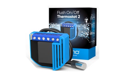
Product Image
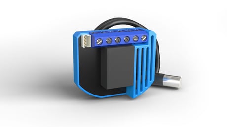
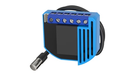
Qubino Thermostat ON/OFF 2
Qubino Thermostat ON/OFF 2 Packaging


1 - Parameter no. 1 – Input I1 switch type
With this parameter, you can select between push-button (momentary) and on/off toggle switch types. Values (size is 1 byte dec): • default value 1 • 0 - push-button (momentary) • 1 - on/off toggle switchSize: 1 byte
Default: 1
Minimum: 0
Maximum: 1
Possible values
| From | To | Desription |
|---|---|---|
| 0 | 1 | With this parameter, you can select between push-button (momentary) and on/off toggle switch types. |
2 - Parameter no. 110 – Temperature Sensor Offset Settings
Set value is added to or subtracted from the actually measured value to adjust the temperature report sent by an external sensor. NOTE1: If configuration parameter 78 (Scale selection) is set to Celsius, then valid interval is -150 – 150 (-15.0 °C – 15.0 °C, resolution 0.1 °C) NOTE2: If configuration parameter 78 (Scale selection) is set to Fahrenheit, then valid interval is -270 - 270 (-27.0 °F – 27.0 °F, resolution 0.1 °F) NOTE3: If configuration parameter 78 (Scale selection) is set to Fahrenheit, note that Fahrenheit values will be converted to Celsius degrees. Due to conversion algorithm please be advised that configuration value could drift when converting values back and forth.Size: 2 bytes
Default: 0
Minimum: -270
Maximum: 270
Possible values
| From | To | Desription |
|---|---|---|
| -270 | 270 | Values (size is 2 byte dec): • default value 0 • -270 - 270 |
4 - Parameter no. 4 – Input 1 contact type
This parameter determines how the switch or push-button is connected.Size: 1 byte
Default: 0
Minimum: 0
Maximum: 1
Possible values
| From | To | Desription |
|---|---|---|
| 0 | 1 | Values (size is 1 byte dec): • default value 0 • 0 - NO (normally open) input type • 1 - NC (normally close) input type |
40 - Parameter no. 40 – Watt Power Consumption Reporting Threshold for Q⬆ Load
Choose by how much power consumption needs to increase or decrease to be reported. Values correspond to percentages so if 10 is set, for example, the device will report any power consumption changes of 10% or more compared to the last reading.Size: 1 byte
Default: 10
Minimum: 1
Maximum: 100
Possible values
| From | To | Desription |
|---|---|---|
| 1 | 100 | Values (size is 1 byte dec): • default value 10 • 0 - Power consumption reporting disabled • 1 - 100 = 1% - 100% Power consumption reporting enabled. New value is reported only when Wattage in real time changes by more than the percentage value set in this parameter compared to the previous Wattage reading, starting at 1% (the lowest value possible). NOTE: Power consumption needs to increase or decrease by at least 1 Watt to be reported, REGARDLESS of percentage set in this parameter. |
42 - Parameter no. 42 – Watt Power Consumption Reporting Time Threshold for Q⬆
Set value refers to the time interval with which power consumption in Watts is reported (30 – 32767 seconds) starting from time of last Watts reported. If for example 300 is entered, energy consumption reports will be sent to the gateway (hub) every 300 seconds (or 5 minutes). EXAMPLE: If we set value to 30 seconds and the device reports Watts because of percent change of power (parameter 40 - Watt Power Consumption Reporting Threshold) at time = 5 seconds, then the device will send next meter report at time = 35 seconds (assuming the device has not sent report within interval 5 to 35 seconds).Size: 2 bytes
Default: 600
Minimum: 0
Maximum: 32767
Possible values
| From | To | Desription |
|---|---|---|
| 0 | 32767 | Values (size is 2 byte dec): • default value 600 (600 seconds = 10 minutes) • 0 - Power consumption reporting disabled • 30 - 32767 = 30 - 32767 seconds. Power consumption reporting enabled. Report is sent according to time interval (value) set here. EXAMPLE: If we set value to 30 s and the device reports Watts because of percent change of power (parameter 40 - Watt Power Consumption Reporting Threshold) at time = 5 seconds, then the device will send next meter report at time = 35 s (assuming the device has not sent report within interval 5 to 35 seconds). |
43 - Parameter no. 43 – Hysteresis Upper temperature offset
This parameter defines minimum temperature difference between real measured temperature and set-point temperature to turn device on in heat mode or turn device off in cool mode.Size: 2 bytes
Default: 5
Minimum: 0
Maximum: 450
Possible values
| From | To | Desription |
|---|---|---|
| 0 | 450 | Values (size is 2 byte dec): • default value 5 (0.5 °C) • 0 – 450 NOTE1: If configuration parameter 78 (Scale selection) is set to Celsius, then valid interval is 0 – 250 (0.0 °C – 25.0 °C, resolution 0.1 °C) NOTE2: If configuration parameter 78 (Scale selection) is set to Fahrenheit, then valid interval is 0 – 450 (0.0 °F – 45.0 °F, resolution 0.1 °F) NOTE3: If configuration parameter 78 (Scale selection) is set to Fahrenheit, note that Fahrenheit values will be converted to Celsius degrees. Due to conversion algorithm please be advised that configuration value could drift when converting values back and forth. |
44 - Parameter no. 44 – Hysteresis Lower temperature offset
This parameter defines minimum temperature difference between real measured temperature and set-point temperature to turn device off in heat mode or turn device on in cool mode. NOTE1: If configuration parameter 78 (Scale selection) is set to Celsius, then valid interval is 0 – 250 (0.0 °C – 25.0 °C, resolution 0.1 °C) NOTE2: If configuration parameter 78 (Scale selection) is set to Fahrenheit, then valid interval is 0 – 450 (0.0 °F – 45.0 °F, resolution 0.1 °F) NOTE3: If configuration parameter 78 (Scale selection) is set to Fahrenheit, note that Fahrenheit values will be converted to Celsius degrees. Due to conversion algorithm please be advised that configuration value could drift when converting values back and forth.Size: 2 bytes
Default: 5
Minimum: 0
Maximum: 450
Possible values
| From | To | Desription |
|---|---|---|
| 0 | 450 | Values (size is 2 byte dec): • default value 5 (0.5 °C) • 0 - 450 NOTE1: If configuration parameter 78 (Scale selection) is set to Celsius, then valid interval is 0 – 250 (0.0 °C – 25.0 °C, resolution 0.1 °C) NOTE2: If configuration parameter 78 (Scale selection) is set to Fahrenheit, then valid interval is 0 – 450 (0.0 °F – 45.0 °F, resolution 0.1 °F) NOTE3: If configuration parameter 78 (Scale selection) is set to Fahrenheit, note that Fahrenheit values will be converted to Celsius degrees. Due to conversion algorithm please be advised that configuration value could drift when converting values back and forth. |
45 - Parameter no. 45 – Antifreeze
Set value determines at which temperature the device will be turned on even (if the thermostat was manually set to off).Size: 2 bytes
Default: 50
Minimum: -125
Maximum: 1000
Possible values
| From | To | Desription |
|---|---|---|
| -125 | 1000 | Values (size is 2 byte dec): • default value 50 (5.0 °C) • -125 – 545 • 1000 - Antifreeze functionality disabled NOTE1: Antifreeze is activated only in heating mode and it uses hysteresis of ±0.5 °C. NOTE2: If configuration parameter 78 (Scale selection) is set to Celsius, then valid interval is -125 – 125 (-12.5 °C – 12.5 °C, resolution 0.1 °C) NOTE3: If configuration parameter 78 (Scale selection) is set to Fahrenheit, then valid interval is 95 – 545 (9.5 °F – 54.5 °F, resolution 0.1 °F) NOTE4: If configuration parameter 78 (Scale selection) is set to Fahrenheit, note that Fahrenheit values will be converted to Celsius degrees. Due to conversion algorithm please be advised that configuration value could drift when converting values back and forth. |
59 - Parameter no. 59 - Thermostat mode
This parameter determines how the device will operate if it will operate in the heating mode or in the cooling mode. The range of the hysteresis will remain the same, only operation will change from heating to cooling and vice versa NOTE1: After parameter change, first exclude device (without setting parameters to default value) and then re include the device!Size: 1 byte
Default: 0
Minimum: 0
Maximum: 1
Possible values
| From | To | Desription |
|---|---|---|
| 0 | 1 | Values (size is 1 byte dec): • default value 0 • 0 - Heat mode • 1 - Cool mode NOTE1: After parameter change, first exclude device (without setting parameters to default value) and then re include the device! |
60 - Parameter no. 60 – Too low temperature limit
This parameter determines the temperature at which the device sends a command to the associated device - to turn ON device or to turn OFF device. NOTE1: Too low temperature limit is used with Association Group 3. NOTE2: If configuration parameter 78 (Scale selection) is set to Celsius, then valid interval is -150 – 1000 (-15.0 °C – 100.0 °C, resolution 0.1 °C) NOTE3: If configuration parameter 78 (Scale selection) is set to Fahrenheit, then valid interval is 50 – 2120 (5.0 °F – 212.0 °F, resolution 0.1 °F) NOTE4: If configuration parameter 78 (Scale selection) is set to Fahrenheit, note that Fahrenheit values will be converted to Celsius degrees. Due to conversion algorithm please be advised that configuration value could drift when converting values back and forth.Size: 2 bytes
Default: 50
Minimum: -150
Maximum: 2120
Possible values
| From | To | Desription |
|---|---|---|
| -150 | 2120 | Values (size is 2 byte dec): • Default value 50 (Too low temperature limit is 5.0 °C) • -150 – 2120 NOTE1: Too low temperature limit is used with Association Group 3. NOTE2: If configuration parameter 78 (Scale selection) is set to Celsius, then valid interval is -150 – 1000 (-15.0 °C – 100.0 °C, resolution 0.1 °C) NOTE3: If configuration parameter 78 (Scale selection) is set to Fahrenheit, then valid interval is 50 – 2120 (5.0 °F – 212.0 °F, resolution 0.1 °F) NOTE4: If configuration parameter 78 (Scale selection) is set to Fahrenheit, note that Fahrenheit values will be converted to Celsius degrees. Due to conversion algorithm please be advised that configuration value could drift when converting values back and forth. |
61 - Parameter no. 61 – Too high temperature limit
This parameter determines the temperature at which the device sends a command to the associated device, to turn ON device or to turn OFF device. NOTE1: Too high temperature limit is used with Association Group 3. NOTE2: If configuration parameter 78 (Scale selection) is set to Celsius, then valid interval is 1 – 1000 (0.1 °C – 100.0 °C, resolution 0.1 °C) NOTE3: If configuration parameter 78 (Scale selection) is set to Fahrenheit, then valid interval is 322 – 2120 (32.2 °F – 212.0 °F, resolution 0.1 °F) NOTE4: If configuration parameter 78 (Scale selection) is set to Fahrenheit, note that Fahrenheit values will be converted to Celsius degrees. Due to conversion algorithm please be advised that configuration value could drift when converting values back and forth.Size: 2 bytes
Default: 700
Minimum: 1
Maximum: 2120
Possible values
| From | To | Desription |
|---|---|---|
| 1 | 2120 | Values (size is 2 byte dec): • default value 700 (too high temperature limit is 70.0 °C) • 1 – 2120 NOTE1: Too high temperature limit is used with Association Group 3. NOTE2: If configuration parameter 78 (Scale selection) is set to Celsius, then valid interval is 1 – 1000 (0.1 °C – 100.0 °C, resolution 0.1 °C) NOTE3: If configuration parameter 78 (Scale selection) is set to Fahrenheit, then valid interval is 322 – 2120 (32.2 °F – 212.0 °F, resolution 0.1 °F) NOTE4: If configuration parameter 78 (Scale selection) is set to Fahrenheit, note that Fahrenheit values will be converted to Celsius degrees. Due to conversion algorithm please be advised that configuration value could drift when converting values back and forth. |
63 - Parameter no. 63 – Output switch selection
Set value determines the type of the device connected to the on/off output. The output type can be normally open (NO) or normally closed (NC).Size: 1 byte
Default: 0
Minimum: 0
Maximum: 1
Possible values
| From | To | Desription |
|---|---|---|
| 0 | 1 | Values (size is 1 byte dec): • default value 0 • 0 - When switch/device is off the output is 0 V (NC). • 1 - When switch/device is off the output is 240 Vac or 24 Vdc (NO). |
78 - Parameter no. 78 – Scale Selection
This parameter determines in which measurement unit the device will report temperature (Fahrenheit or Celsius) and determines the scale the configuration parameters (43, 44, 44, 45, 60, 61, 110, 120) are interpreted as. NOTE1: This scale has influence on Temperature reporting. The device is capable of receiving a Set point in all supported scales. NOTE2: This configuration parameter has impact on configuration parameters 43, 44, 44, 45, 60, 61, 110, 120. If scale is set to degrees Fahrenheit configuration values at parameters 43, 44, 44, 45, 60, 61, 110, 120 will be converted to degrees Celsius. Please note that converted values could drift when converting values back and forth.Size: 1 byte
Default: 0
Minimum: 0
Maximum: 1
Possible values
| From | To | Desription |
|---|---|---|
| 0 | 1 | Values (size is 1 byte dec): • Default value 0 = degrees Celsius • 0 = degrees Celsius • 1 = degrees Fahrenheit |
110 - Parameter no. 110 – Temperature Sensor Offset Settings
Set value is added to or subtracted from the actually measured value to adjust the temperature report sent by an external sensor. NOTE1: If configuration parameter 78 (Scale selection) is set to Celsius, then valid interval is -150 – 150 (-15.0 °C – 15.0 °C, resolution 0.1 °C) NOTE2: If configuration parameter 78 (Scale selection) is set to Fahrenheit, then valid interval is -270 - 270 (-27.0 °F – 27.0 °F, resolution 0.1 °F) NOTE3: If configuration parameter 78 (Scale selection) is set to Fahrenheit, note that Fahrenheit values will be converted to Celsius degrees. Due to conversion algorithm please be advised that configuration value could drift when converting values back and forth.Size: 2 bytes
Default: 0
Minimum: -270
Maximum: 270
Possible values
| From | To | Desription |
|---|---|---|
| -270 | 270 | Values (size is 2 byte dec): • default value 0 • -270 - 270 NOTE1: If configuration parameter 78 (Scale selection) is set to Celsius, then valid interval is -150 – 150 (-15.0 °C – 15.0 °C, resolution 0.1 °C) NOTE2: If configuration parameter 78 (Scale selection) is set to Fahrenheit, then valid interval is -270 - 270 (-27.0 °F – 27.0 °F, resolution 0.1 °F) NOTE3: If configuration parameter 78 (Scale selection) is set to Fahrenheit, note that Fahrenheit values will be converted to Celsius degrees. Due to conversion algorithm please be advised that configuration value could drift when converting values back and forth. |
120 - Parameter no. 120 – Temperature Sensor Reporting Threshold
This configuration parameters sets reporting threshold between reported temperature and actual temperature for reporting temperature at association group 4.Size: 2 bytes
Default: 5
Minimum: 0
Maximum: 270
Possible values
| From | To | Desription |
|---|---|---|
| 0 | 270 | Values (size is 2 byte dec): • Default value 5 = 0.5°C • 0 – Reporting disabled • 0 – 270 NOTE1: If configuration parameter 78 (Scale selection) is set to Celsius, then valid interval is 0 – 150 (0 °C – 15.0 °C, resolution 0.1 °C) NOTE2: If configuration parameter 78 (Scale selection) is set to Fahrenheit, then valid interval is 0 - 270 (0 °F – 27.0 °F, resolution 0.1 °F) NOTE3: If configuration parameter 78 (Scale selection) is set to Fahrenheit, note that Fahrenheit values will be converted to Celsius degrees. Due to conversion algorithm please be advised that configuration value could drift when converting values back and forth. |
MANUAL INCLUSION 1. Enable add/remove mode on your Z-Wave gateway (hub) 2. Connect the device to the power supply (with the temperature sensor already connected*) 3. Toggle the switch connected to the I1 terminal 3 times within 3 seconds (1 click per second). The device has to get On/Off signal 3 times, meaning 3 times push of the push button or with the normal button 3 times On/Off . 4. Inclusion with the switch connected to I1 terminal is not limited by time
Z-WAVE EXCLUSION 1. Connect the device to the power supply 2. Make sure the device is within direct range of your Z-Wave gateway (hub) or use a hand-held Z-Wave remote to perform exclusion 3. Enable exclusion mode on your Z-Wave gateway (hub) 4. Toggle the switch connected to the I1 terminal 3 times within 3 seconds 5. Exclusion with the switch connected to I1 terminal is not limited by time
FACTORY RESET 1. Connect the device to the power supply 2. Within the first minute the device is connected to the power supply, toggle the switch connected to the I1 terminal 5 times within 5 seconds
1. Scan QR code on device label and add S2 DSK to Provisioning List in gateway (hub) 2. Connect the device to the power supply (with the temperature sensor already connected) 3. Inclusion will be initiated automatically within few seconds of connection to the power supply and the device will automatically enrol in your network (when the device is excluded and connected to the power supply it automatically enters the LEARN MODE state).
| Type | Value(s) |
|---|
| Group | Type |
|---|---|
| Power Management | Over-load status: Over-load detected |
| Sensor type |
|---|
| Air Temperature |
| Meter type |
|---|
| Electric Meter Consumption |