Heatit controls
Heatit Z-TRM3
Z-TRM3
Thermostat - HVAC
HW: 3 FW: 4.00:04.00
ZM5101
6.81.06
0x019B (411)
0x0003 (3)
0x0203 (515)
ZC10-20036889
2020-03-16 18:09:15.343262
N/A
Enhanced 232 Slave
Always On Slave
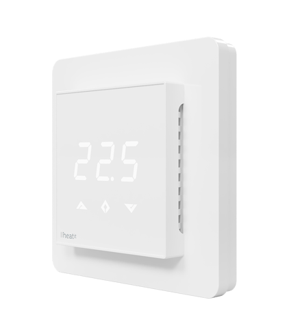
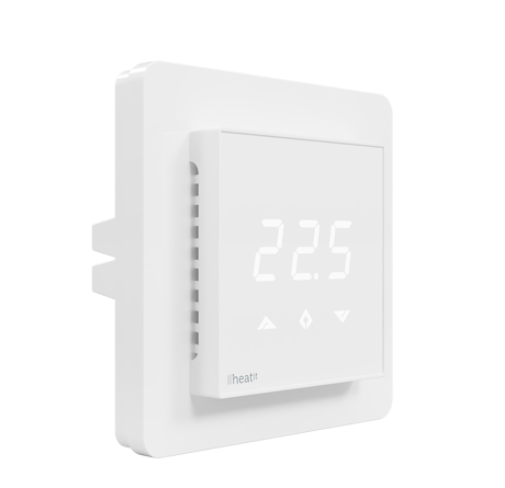
Heatit Z-TRM3 is an electronic thermostat for electrical floor heating, designed to be mounted in a standard flush box. The thermostat has a built-in Z-Wave chip that can be connected with Home Automation systems. Heatit Z-TRM3 has SmartStart.
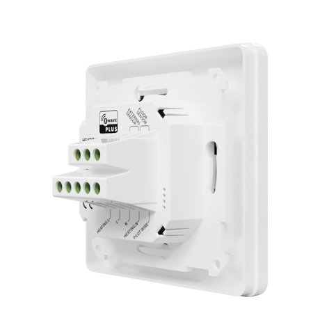
Heatit Z-TRM3 is an electronic thermostat for electrical floor heating, designed to be mounted in a standard flush box. The thermostat has a built-in Z-Wave chip that can be connected with Home Automation systems. Heatit Z-TRM3 has SmartStart. This feature allows the user to include all devices with SmartStart by scanning the QR codes on the devices. On startup all the devices will automatically be included in the gateway (requires SmartStart compability). This saves the installer a lot of work. Heatit Z-TRM3 is equipped with a single pole switch and fits into System 55 frames. The thermostat can withstand a load of max 16A /3600W at 230V. At higher loads the thermostat must control a contactor. The thermostat may be connected to two wired external sensors. The thermostat has the capacity of up to 5 associations (relays, wall plugs etc.). The thermostat is designed for electrical heating. It may be used for waterbased heating if the thermostat is linked with the Heatit Z-Water.
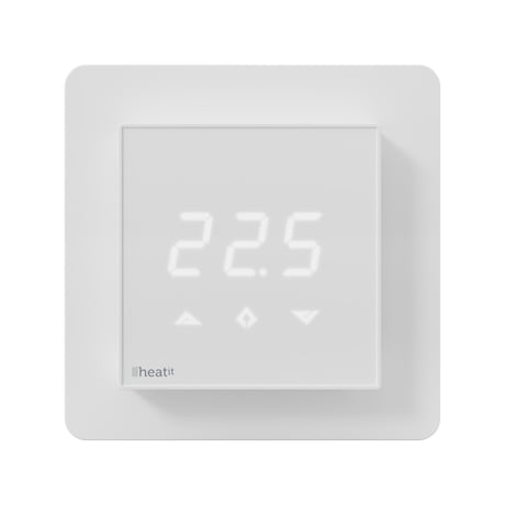
Product Image


1 - Operation mode
Operation modeSize: 1 byte
Default: 1
Minimum: 0
Maximum: 1
Possible values
| From | To | Desription |
|---|---|---|
| 0 | 0 | Off |
| 1 | 1 | Heating mode (Default) |
2 - Sensor mode
Sensor modeSize: 1 byte
Default: 1
Minimum: 0
Maximum: 4
Possible values
| From | To | Desription |
|---|---|---|
| 0 | 0 | F-mode, floor sensor mode |
| 1 | 1 | A-mode, internal room sensor mode (Default) |
| 2 | 2 | AF-mode, internal room sensor with floor limitation |
| 3 | 3 | A2-mode, external room sensor mode |
| 4 | 4 | A2F-mode, external sensor with floor limitation |
3 - Floor sensor type
Floor sensor typeSize: 1 byte
Default: 0
Minimum: 0
Maximum: 5
Possible values
| From | To | Desription |
|---|---|---|
| 0 | 0 | 10K NTC (Default) |
| 1 | 1 | 12K NTC |
| 2 | 2 | 15K NTC |
| 3 | 3 | 22K NTC |
| 4 | 4 | 33K NTC |
| 5 | 5 | 47K NTC |
4 - Temperature control hysteresis (DIFF I)
Temperature control hysteresis (DIFF I)Size: 1 byte
Default: 5
Minimum: 3
Maximum: 30
Possible values
| From | To | Desription |
|---|---|---|
| 3 | 30 | 0.3°C to 3.0°C. Default is 5 (0.5°C) |
5 - Floor minimum temperature limit (FLo)
Floor minimum temperature limit (FLo)Size: 2 bytes
Default: 50
Minimum: 50
Maximum: 400
Possible values
| From | To | Desription |
|---|---|---|
| 50 | 400 | 5.0°C to 40.0°C. Default is 50 (5.0°C) |
6 - Floor maximum temperature limit (FHi)
Floor maximum temperature limit (FHi)Size: 2 bytes
Default: 400
Minimum: 50
Maximum: 400
Possible values
| From | To | Desription |
|---|---|---|
| 50 | 400 | 5.0°C to 40.0°C. Default is 400 (40.0°C) |
7 - Air (A2) minimum temperature limit (ALo)
Air (A2) minimum temperature limit (ALo)Size: 2 bytes
Default: 50
Minimum: 50
Maximum: 400
Possible values
| From | To | Desription |
|---|---|---|
| 50 | 400 | 5.0°C to 40.0°C. Default is 50 (5.0°C) |
8 - Air (A2) maximum temperature limit (AHi)
Air (A2) maximum temperature limit (AHi)Size: 2 bytes
Default: 400
Minimum: 50
Maximum: 400
Possible values
| From | To | Desription |
|---|---|---|
| 50 | 400 | 5.0°C to 40.0°C. Default is 400 (40.0°C) |
9 - Heating mode setpoint
Heating mode setpointSize: 2 bytes
Default: 210
Minimum: 50
Maximum: 400
Possible values
| From | To | Desription |
|---|---|---|
| 50 | 400 | 5.0°C to 40.0°C. Default is 210 (21.0°C) |
10 - Room sensor calibration (A)
Room sensor calibration (A) NB. To set a negative value, use 256 and subtract the desired value.Size: 1 byte
Default: 0
Minimum: -60
Maximum: 60
Possible values
| From | To | Desription |
|---|---|---|
| -60 | 60 | -6.0°C to 6.0°C. Default is 0 (0.0°C) |
11 - Floor sensor calibration
Floor sensor calibration. NB. To set a negative value, use 256 and subtract the desired value.Size: 1 byte
Default: 0
Minimum: -60
Maximum: 60
Possible values
| From | To | Desription |
|---|---|---|
| -60 | 60 | -6.0°C to 6.0°C. Default is 0 (0.0°C) |
12 - External sensor calibration
External sensor calibration. NB. To set a negative value, use 256 and subtract the desired value.Size: 1 byte
Default: 0
Minimum: -60
Maximum: 60
Possible values
| From | To | Desription |
|---|---|---|
| -60 | 60 | -6.0°C to 6.0°C. Default is 0 (0.0°C) |
13 - Temperature display
Temperature display. Selects which temperature is shown on the display. Refer to Chapter 11 ”Standby and main screen”.Size: 1 byte
Default: 0
Minimum: 0
Maximum: 1
Possible values
| From | To | Desription |
|---|---|---|
| 0 | 0 | Display setpoint temperature (Default) |
| 1 | 1 | Display measured temperature |
14 - Button brightness – dimmed state
Button brightness – dimmed state. Configure the brightness of the buttons in dimmed state.Size: 1 byte
Default: 50
Minimum: 0
Maximum: 100
Possible values
| From | To | Desription |
|---|---|---|
| 0 | 100 | 0 to 100% (Default 50%) |
15 - Button brightness – active state
Button brightness – active state. Configure the brightness of the buttons in active state.Size: 1 byte
Default: 100
Minimum: 0
Maximum: 100
Possible values
| From | To | Desription |
|---|---|---|
| 0 | 100 | 0 to 100% (Default 100%) |
16 - Display brightness – dimmed state
Display brightness – dimmed state. Configure the brightness of the display in dimmed state.Size: 1 byte
Default: 50
Minimum: 0
Maximum: 100
Possible values
| From | To | Desription |
|---|---|---|
| 0 | 100 | 0 to 100% (Default 50%) |
17 - Display brightness – active state
Display brightness – active state. Configure the brightness of the display, in active state.Size: 1 byte
Default: 100
Minimum: 0
Maximum: 100
Possible values
| From | To | Desription |
|---|---|---|
| 0 | 100 | 0 to 100% (Default 100%) |
18 - Temperature report interval
Temperature report interval. Time interval between consecutive temperature reports. Temperature reports can also be sent as a result of polling.Size: 2 bytes
Default: 60
Minimum: 30
Maximum: 32767
Possible values
| From | To | Desription |
|---|---|---|
| 30 | 32767 | 30 seconds to 32767 seconds. Default is 60 seconds |
19 - Temperature report hysteresis
Temperature report hysteresis. The temperature report will be sent if there is a difference in temperature value from the previous value reported, defined in this parameter (hysteresis). Temperature reports can also be sent as a result of polling.Size: 1 byte
Default: 10
Minimum: 1
Maximum: 100
Possible values
| From | To | Desription |
|---|---|---|
| 1 | 100 | 0.1°C to 10.0°C. Default is 10 (1.0°C) |
20 - Meter report interval.
Meter report interval. Time interval between consecutive meter reports. Meter reports can also be sent as a result of polling.Size: 2 bytes
Default: 90
Minimum: 30
Maximum: 32767
Possible values
| From | To | Desription |
|---|---|---|
| 30 | 32767 | 30 seconds to 32767 seconds. Default is 90 seconds |
21 - Meter report delta value
Meter report delta value. Delta value in kWh between consecutive meter reports. Meter reports can also be sent as a result of polling.Size: 1 byte
Default: 10
Minimum: 0
Maximum: 255
Possible values
| From | To | Desription |
|---|---|---|
| 0 | 0 | Reporting meter based on change is disabled |
| 255 | 255 | A delta value of 0 to 25.5 kWh will result in a metering report. Default is 10 (1.0 kWh) |
Add. The primary controller/gateway has a mode for adding devices. Please refer to your primary controller manual on how to set the primary controller in add mode. The device may only be added from the network if the primary controller is in add mode. There are two ways to add the Heatit Z-TRM3 to a Z-Wave network. METHOD 1: STANDARD (MANUAL) 1. Press Center (confirm) for 10 seconds. The display will show OFF. 2. Press Right (down) 5 times until you see Con on the display. 3. Start the add/remove device process in your primary controller. 4. Start the add/remove mode in the Heatit Z-TRM3 by pressing Center (confirm) for approximately 2 seconds. Adding mode is indicated on the display by rotating LED segments on the display. This lasts until the timeout occurs after 90 seconds, or until the module has been added in the network. Confirmation will show Inc/EcL on the display. Exit programming mode by choosing ESC in the menu. Your thermostat is now ready for use with default settings. METHOD 2: SMARTSTART (AUTOMATIC) SmartStart enabled products can be added into a Z-Wave network by scanning the Z-Wave QR-Code present on the product with a controller providing SmartStart inclusion. No further action is required and the SmartStart product will be added automatically within 10 minutes of being switched on in the network vicinity.
Remove. The primary controller/gateway has a mode for removing devices. Please refer to your primary controller manual on how to set the primary controller in remove mode. The device may only be removed from the network if the primary controller is in remove mode. When the device is removed from the network, it will NOT revert to factory settings. Removing mode is indicated on the display by rotating LED segments on the display. This lasts until the timeout occurs after 90 seconds, or until the module has been added/removed in the network. Confirmation will show Inc/EcL on the display. Exit programming mode by choosing ESC in the menu. Your thermostat is now ready for use with default settings. NB! When the thermostat is removed from the gateway, the parameters are not reset.
By pressing buttons Right and Center (down and confirm) for 20 seconds, the thermostat will perform a complete factory reset. NB! Please use this procedure only when the primary controller/gateway is missing or otherwise inoperable. The device will display rES for 10 seconds while performing a factory reset. When rES no longer is displayed, the thermostat has been reset.
Chapter 8. Principles of regulation Chapter 11. Standby and main screen Chapter 12. Choice of sensor Chapter 13. Selecting the right value for your external floor sensor Chapter 14. Calibration Chapter 17. Min/Max temperature settings Chapter 18.1 Display on/off Chapter 18.2 Childlock
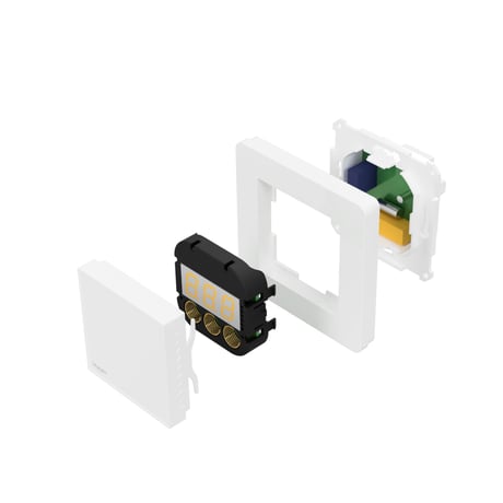
The Z-Wave DSK can be found in the QR-Code and is located in 3 locations; 1. On the product box. 2. On the physical product, placed on the black plastic underneath the front. 3. On the PCB internally.
| Type | Value(s) |
|---|
| Sensor type |
|---|
| Air Temperature |
| Sensor type |
|---|
| Air Temperature |
| Meter type |
|---|
| Electric Meter Consumption |