LEEDARSON
Bypass Door Window Sensor Z-Wave 700
7AA-SS-VE-C0
Notification Sensor
HW: 1 FW: 1.33
ZGM130
7.12.2
0x0300 (768)
0x0300 (768)
0x0041 (65)
ZC12-20030038
2020-03-20 13:20:37.53224
N/A
Enhanced 232 Slave
Reporting Sleeping Slave
Bypass Door Window Sensor Z-Wave 700
the door window sensor lets you know when door or windows is opened and can trigger different actions in response to that open action (or close action).
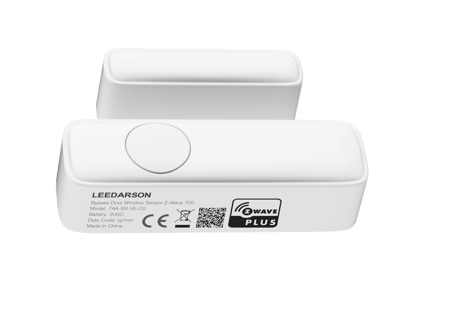
Product Image


1 - 7210Range
Set the range about magnetic field Range: 0-the range of parameter 0x02 is 0x00000001-0x00004B00, the range of parameter 0x03 is 0x00000001-0x00002300. 1- the range of parameter 0x02 is 0x00000001-0x0002EE00, the range of parameter 0x03 is 0x00000001-0x00015E00.Size: 1 byte
Default: 0
Minimum: 0
Maximum: 1
Possible values
| From | To | Desription |
|---|---|---|
| 0 | 1 | 0-the range of parameter 0x02 is 0x00000001-0x00004B00 and the range of parameter 0x03 is 0x00000001-0x00002300. 1- the range of parameter 0x02 is 0x00000001-0x0002EE00 and the range of parameter 0x03 is 0x00000001-0x00015E00. |
2 - 7210OP
7210OP Set the average magnetic field in ut Range: 0x00000001-0x00004B00 or 0x00000001-0x0002EE00Size: 4 bytes
Default: 640
Minimum: 1
Maximum: 19200
Possible values
| From | To | Desription |
|---|---|---|
| 1 | 19200 | the average magnetic field. 0x00000001 means that the magnetic field is 1 ut, 0x0002EE00 means that the magnetic field is 192000 ut |
3 - 7210PolHyst
Set the offset about magnetic field Range: 0x00000001-0x00002300 or 0x00000001-0x00015E00Size: 4 bytes
Default: 200
Minimum: 1
Maximum: 8960
Possible values
| From | To | Desription |
|---|---|---|
| 1 | 8960 | the offset of the magnetic field. 0x00000001 means that the magnetic field is 1 ut, 0x0002EE00 means that the magnetic field is 89600 ut |
10 - LowBatPrecent
This parameter defines a battery level as the “low battery”. Range: 0x05-0x32Size: 1 byte
Default: 10
Minimum: 5
Maximum: 50
Possible values
| From | To | Desription |
|---|---|---|
| 5 | 50 | 0x0A defines the low battery level. 0x05 means that device will send a low level alarm report when the battery levle is less than 5%. 0x32 means that device will send a low level alarm report when the battery levle is less than 50%. |
14 - BasicEnable
Enable/Disable BASIC SET command 0 – Disable. 1 – Enable.Size: 1 byte
Default: 0
Minimum: 0
Maximum: 1
Possible values
| From | To | Desription |
|---|---|---|
| 0 | 1 | parameter 14 will disable/enable the basic set command when it is triggered. the value 0 means that sensor will not send basic set command when the sensor is triggered, value 1 means that the sensor willl send basic set command when it is triggered. |
15 - BasicReverse
Door Sensor reverse its value of BASIC SET when the magnet is triggered. 0 -Send BASIC SET VALUE = 0xFF/0x00 to nodes associated with group 2 when door is opened/closed. 1 –Send BASIC SET VALUE = 0/255 to nodes associated with group 2 when door is opened/closed.Size: 1 byte
Default: 0
Minimum: 0
Maximum: 1
Possible values
| From | To | Desription |
|---|---|---|
| 0 | 1 | 0 -Send BASIC SET VALUE = 0xFF/0x00 to nodes associated with group 2 when door is opened/closed. 1 –Send BASIC SET VALUE = 0/255 to nodes associated with group 2 when door is opened/closed. |
20 - Bypass
Enable/Disable Bypass mode 0 – Enable. 1 – Disable.Size: 1 byte
Default: 1
Minimum: 0
Maximum: 1
Possible values
| From | To | Desription |
|---|---|---|
| 0 | 1 | parameter 20 disable/enable the bypass mode. the value 0 means that sensor will enter a bypass mode when the bypass button is pressed, value 0 means that sensor will not enter bypass mode when the bypass button is pressed |
21 - temp
The interval time the Door Sensor reports the Multilevel Sensor Report to association group1 in minutes. 0x0F-0xFFSize: 1 byte
Default: 15
Minimum: 15
Maximum: 127
Possible values
| From | To | Desription |
|---|---|---|
| 15 | 127 | parameter 0x21 assign the time the sensor send the temperature report to associated node in minute. For example 0x10 means that sensor will send a temperature report every 14 mins |
254 - LockConfig
Enable/Disable configuration set 0 – Enable. 1 – Disable.Size: 1 byte
Default: 0
Minimum: 0
Maximum: 1
Possible values
| From | To | Desription |
|---|---|---|
| 0 | 1 | parameter 0xFE disable/enable the configuration set function. value 0 means that any configuration set will be disabled, value 1 means that configuration set will be enbale,you can change the values of the configration parameters |
1. Power on your Door Sensor, set your Z-Wave controller into add/inclusion mode. 2. Trigger this action 3. LED will flash green during the inclusion, and then solid green for 2 seconds to indicate the inclusion is successful, otherwise the LED will solid red for 2 seconds in which you need to repeat the process form step 2
1. Power on your Door Sensor, and let the Z-Wave primary controller into remove/exclusion mode. 2. Trigger this action. 3. LED will flash red during the exclusion, and then solid red for 2 seconds to indicate that the exclusion is successful, otherwise the LED will solid green for 2 seconds in which you need to repeat the process form step 2.
Power on: In the network: Send Battery report and Wake up notification, the LED will solid green within 1 second. Not in the network: Only the LED will blink red for three times and then off. Short press button one time : In the network: Send Wake up notification, and green LED will fast blink when sending data, and turn off once send completed. But if it don’t receive ack from gateway, the green led will blink for 10 seconds. Not in the network: NOP
Reset Contact Sensor to factory default. NOTE: 1. Triggering this action, the red LED will be accelerate blink in 5 seconds. After 5 seconds, the red LED will remain on until the key is released. Contact Sensor will send “Device_Reset_Locally” to the main controller and exclude from the Z-Wave network when the button is released, this procedure will reset the sensor to factory default. 2. Please use this procedure only when the network primary controller is missing or otherwise inoperable. 3. When not in the network, triggering this action, the red LED will be accelerate blink in 5 seconds. After 5 seconds, the red LED will remain on until the key is released, this procedure will reset the sensor to factory default.
on the side of product
pls chekc the user manual on page 9
NA
| Group | Type |
|---|---|
| Access Control |
|
| Home Security |
|
| Power Management |
|
| Sensor type |
|---|
| General Purpose |