HELTUN
Relay Switch Quinto
HE-RS01
Central Scene Device
HW: 76 FW: 1.01
ZGM130
7.11.1
0x0344 (836)
0x0004 (4)
0x0009 (9)
ZC12-20040046
2020-04-15 23:03:55.152914
N/A
Enhanced 232 Slave
Always On Slave
Advanced Programmable Z-Wave Plus v2 In-Wall Relay Switch—with S2 security and SmartStart on the Z-Wave 700 platform.
The HELTUN HE-RS01 is an advanced programmable Z-Wave Plus v2 in-wall relay switch that controls many devices, including lights, dimmers, blinds, curtains, door locks, gates, motorized valves, roller shutters, and more. Features: • Five-channel 5-amp relays with dry contact inputs • Each relay may be controlled by a timer or on a week schedule • Power Consumption logic monitors energy usage • 10 association groups • Incorporates HELTUN Advanced Zero-Cross Technology The HELTUN HE-RS01 is part of an entire line of smart, connected products designed to provide the best technology has to offer without compromising stylish living.
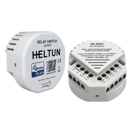
Product Picture as Published
.jpg)
On a Din Rail
.jpg)
Control Inputs
.jpg)
Sizes
.jpg)
Installation
.jpg)
Use Cases


1 - TIME CORRECTION
Time correction by controllerSize: 1 byte
Default: 1
Minimum: 0
Maximum: 1
Possible values
| From | To | Desription |
|---|---|---|
| 0 | 0 | Switch off auto-correction |
| 1 | 0 | If TPS05 is connected to a Z-Wave gateway, the time and day will be periodically polled and corrected from the gateway |
2 - WEEKDAY
The day of the week (starting from Monday)Size: 1 byte
Default: 1
Minimum: 1
Maximum: 7
Possible values
| From | To | Desription |
|---|---|---|
| 1 | 0 | Monday |
| 2 | 0 | Tuesday |
| 3 | 0 | Wednesday |
| 4 | 0 | Thursday |
| 5 | 0 | Friday |
| 6 | 0 | Saturday |
| 7 | 0 | Sunday |
3 - HOUR
Time HourSize: 1 byte
Default: 0
Minimum: 0
Maximum: 23
Possible values
| From | To | Desription |
|---|---|---|
| 0 | 23 | Time Hour in 24 hour format |
4 - MINUTE
Time MinuteSize: 1 byte
Default: 0
Minimum: 0
Maximum: 59
Possible values
| From | To | Desription |
|---|---|---|
| 0 | 59 | Manual adjustment of time minutes (60 minutes) |
5 - METER REPORT INTERVAL
Energy Consumption Meter Consecutive Report Interval, minutesSize: 1 byte
Default: 10
Minimum: 1
Maximum: 120
Possible values
| From | To | Desription |
|---|---|---|
| 1 | 120 | Energy Consumption Meter Consecutive Report Interval in Minutes |
6 - RELAY1 CONTROL SOURCE
Relay 1 control sourceSize: 1 byte
Default: 1
Minimum: 0
Maximum: 5
Possible values
| From | To | Desription |
|---|---|---|
| 0 | 0 | Controlled by gateway or associated device |
| 1 | 1 | Controlled by touch button N1 (Top Left) |
| 2 | 2 | Controlled by touch button N2 (Top Right) |
| 3 | 3 | Controlled by touch button N3 (Bottom Left) |
| 4 | 4 | Controlled by touch button N4 (Bottom Right) |
| 5 | 5 | Controlled by touch button N5 (Center) |
7 - RELAY2 CONTROL SOURCE
Relay 2 control sourceSize: 1 byte
Default: 2
Minimum: 0
Maximum: 5
Possible values
| From | To | Desription |
|---|---|---|
| 0 | 0 | Controlled by gateway or associated device |
| 1 | 1 | Controlled by touch button N1 (Top Left) |
| 2 | 2 | Controlled by touch button N2 (Top Right) |
| 3 | 3 | Controlled by touch button N3 (Bottom Left) |
| 4 | 4 | Controlled by touch button N4 (Bottom Right) |
| 5 | 5 | Controlled by touch button N5 (Center) |
8 - RELAY3 CONTROL SOURCE
Relay 3 control sourceSize: 1 byte
Default: 3
Minimum: 0
Maximum: 5
Possible values
| From | To | Desription |
|---|---|---|
| 0 | 0 | Controlled by gateway or associated device |
| 1 | 1 | Controlled by touch button N1 (Top Left) |
| 2 | 2 | Controlled by touch button N2 (Top Right) |
| 3 | 3 | Controlled by touch button N3 (Bottom Left) |
| 4 | 4 | Controlled by touch button N4 (Bottom Right) |
| 5 | 5 | Controlled by touch button N5 (Center) |
9 - RELAY4 CONTROL SOURCE
Relay 4 control sourceSize: 1 byte
Default: 4
Minimum: 0
Maximum: 5
Possible values
| From | To | Desription |
|---|---|---|
| 0 | 0 | Controlled by gateway or associated device |
| 1 | 1 | Controlled by touch button N1 (Top Left) |
| 2 | 2 | Controlled by touch button N2 (Top Right) |
| 3 | 3 | Controlled by touch button N3 (Bottom Left) |
| 4 | 4 | Controlled by touch button N4 (Bottom Right) |
| 5 | 5 | Controlled by touch button N5 (Center) |
10 - RELAY5 CONTROL SOURCE
Relay 5 control sourceSize: 1 byte
Default: 5
Minimum: 0
Maximum: 5
Possible values
| From | To | Desription |
|---|---|---|
| 0 | 0 | Controlled by gateway or associated device |
| 1 | 1 | Controlled by touch button N1 (Top Left) |
| 2 | 2 | Controlled by touch button N2 (Top Right) |
| 3 | 3 | Controlled by touch button N3 (Bottom Left) |
| 4 | 4 | Controlled by touch button N4 (Bottom Right) |
| 5 | 5 | Controlled by touch button N5 (Center) |
11 - HOLD1 CONTROL MODE
Hold control mode for touch button 1Size: 1 byte
Default: 1
Minimum: 0
Maximum: 3
Possible values
| From | To | Desription |
|---|---|---|
| 0 | 0 | Hold function is disabled |
| 1 | 1 | Operate like click |
| 2 | 2 | When the button is held the relay output state is ON, as soon as the button is released the relay output state changes to OFF (momentary switch). |
| 3 | 3 | When the button is held the relay output state is OFF, as soon as the button is released the relay output state changes to ON (momentary switch). |
12 - HOLD2 CONTROL MODE
Hold control mode for touch button 2Size: 1 byte
Default: 1
Minimum: 0
Maximum: 3
Possible values
| From | To | Desription |
|---|---|---|
| 0 | 0 | Hold function is disabled |
| 1 | 1 | Operate like click |
| 2 | 2 | When the button is held the relay output state is ON, as soon as the button is released the relay output state changes to OFF (momentary switch). |
| 3 | 3 | When the button is held the relay output state is OFF, as soon as the button is released the relay output state changes to ON (momentary switch). |
13 - HOLD3 CONTROL MODE
Hold control mode for touch button 3Size: 1 byte
Default: 1
Minimum: 0
Maximum: 3
Possible values
| From | To | Desription |
|---|---|---|
| 0 | 0 | Hold function is disabled |
| 1 | 1 | Operate like click |
| 2 | 2 | When the button is held the relay output state is ON, as soon as the button is released the relay output state changes to OFF (momentary switch). |
| 3 | 3 | When the button is held the relay output state is OFF, as soon as the button is released the relay output state changes to ON (momentary switch). |
14 - HOLD4 CONTROL MODE
Hold control mode for touch button 4Size: 1 byte
Default: 1
Minimum: 0
Maximum: 3
Possible values
| From | To | Desription |
|---|---|---|
| 0 | 0 | Hold function is disabled |
| 1 | 1 | Operate like click |
| 2 | 2 | When the button is held the relay output state is ON, as soon as the button is released the relay output state changes to OFF (momentary switch). |
| 3 | 3 | When the button is held the relay output state is OFF, as soon as the button is released the relay output state changes to ON (momentary switch). |
15 - HOLD5 CONTROL MODE
Hold control mode for touch button 5Size: 1 byte
Default: 1
Minimum: 0
Maximum: 3
Possible values
| From | To | Desription |
|---|---|---|
| 0 | 0 | Hold function is disabled |
| 1 | 1 | Operate like click |
| 2 | 2 | When the button is held the relay output state is ON, as soon as the button is released the relay output state changes to OFF (momentary switch). |
| 3 | 3 | When the button is held the relay output state is OFF, as soon as the button is released the relay output state changes to ON (momentary switch). |
16 - CLICK1 CONTROL MODE
Click control mode for touch button 1Size: 1 byte
Default: 1
Minimum: 0
Maximum: 6
Possible values
| From | To | Desription |
|---|---|---|
| 0 | 0 | Click function disabled |
| 1 | 1 | Relay inverts state (toggles ON to OFF, OFF to ON). |
| 2 | 2 | Relay inverts state (toggles ON to OFF, OFF to ON) according to the button backlight state. |
| 3 | 3 | Relay switches to ON state only. |
| 4 | 4 | Relay switches to OFF state only. |
| 5 | 5 | Timer: On>Off Mode: Relay output switches to ON state (contacts are closed) then after a specified time switches back to OFF state (contacts are open). The time is specified in parameters 35-39. |
| 6 | 6 | Timer: OFF>ON Mode: Relay output switches to OFF state (contacts are open) then after a specified time switches back to ON state (contacts are closed). The time is specified in Parameters 35-39. |
17 - CLICK2 CONTROL MODE
Click control mode for touch button 2Size: 1 byte
Default: 1
Minimum: 0
Maximum: 6
Possible values
| From | To | Desription |
|---|---|---|
| 0 | 0 | Click function disabled |
| 1 | 1 | Relay inverts state (toggles ON to OFF, OFF to ON). |
| 2 | 2 | Relay inverts state (toggles ON to OFF, OFF to ON) according to the button backlight state. |
| 3 | 3 | Relay switches to ON state only. |
| 4 | 4 | Relay switches to OFF state only. |
| 5 | 5 | Timer: On>Off Mode: Relay output switches to ON state (contacts are closed) then after a specified time switches back to OFF state (contacts are open). The time is specified in parameters 35-39. |
| 6 | 6 | Timer: OFF>ON Mode: Relay output switches to OFF state (contacts are open) then after a specified time switches back to ON state (contacts are closed). The time is specified in Parameters 35-39. |
18 - CLICK3 CONTROL MODE
Click control mode for touch button 3Size: 1 byte
Default: 1
Minimum: 0
Maximum: 6
Possible values
| From | To | Desription |
|---|---|---|
| 0 | 0 | Click function disabled |
| 1 | 1 | Relay inverts state (toggles ON to OFF, OFF to ON). |
| 2 | 2 | Relay inverts state (toggles ON to OFF, OFF to ON) according to the button backlight state. |
| 3 | 3 | Relay switches to ON state only. |
| 4 | 4 | Relay switches to OFF state only. |
| 5 | 5 | Timer: On>Off Mode: Relay output switches to ON state (contacts are closed) then after a specified time switches back to OFF state (contacts are open). The time is specified in parameters 35-39. |
| 6 | 6 | Timer: OFF>ON Mode: Relay output switches to OFF state (contacts are open) then after a specified time switches back to ON state (contacts are closed). The time is specified in Parameters 35-39. |
19 - CLICK4 CONTROL MODE
Click control mode for touch button 4Size: 1 byte
Default: 1
Minimum: 0
Maximum: 6
Possible values
| From | To | Desription |
|---|---|---|
| 0 | 0 | Click function disabled |
| 1 | 1 | Relay inverts state (toggles ON to OFF, OFF to ON). |
| 2 | 2 | Relay inverts state (toggles ON to OFF, OFF to ON) according to the button backlight state. |
| 3 | 3 | Relay switches to ON state only. |
| 4 | 4 | Relay switches to OFF state only. |
| 5 | 5 | Timer: On>Off Mode: Relay output switches to ON state (contacts are closed) then after a specified time switches back to OFF state (contacts are open). The time is specified in parameters 35-39. |
| 6 | 6 | Timer: OFF>ON Mode: Relay output switches to OFF state (contacts are open) then after a specified time switches back to ON state (contacts are closed). The time is specified in Parameters 35-39. |
20 - CLICK5 CONTROL MODE
Click control mode for touch button 5Size: 1 byte
Default: 1
Minimum: 0
Maximum: 6
Possible values
| From | To | Desription |
|---|---|---|
| 0 | 0 | Click function disabled |
| 1 | 1 | Relay inverts state (toggles ON to OFF, OFF to ON). |
| 2 | 2 | Relay inverts state (toggles ON to OFF, OFF to ON) according to the button backlight state. |
| 3 | 3 | Relay switches to ON state only. |
| 4 | 4 | Relay switches to OFF state only. |
| 5 | 5 | Timer: On>Off Mode: Relay output switches to ON state (contacts are closed) then after a specified time switches back to OFF state (contacts are open). The time is specified in parameters 35-39. |
| 6 | 6 | Timer: OFF>ON Mode: Relay output switches to OFF state (contacts are open) then after a specified time switches back to ON state (contacts are closed). The time is specified in Parameters 35-39. |
21 - RELAY1 TIMER DURATION
Timer mode duration for button 1. This parameter specifies the duration in seconds for the Timer mode (value 5 or 6 in Parameters 30). Press the button and the relay output goes to ON/OFF for the specified time then changes back to OFF/ON. This function can be used to open/close garage doors, blinds, curtains, etc. or to turn attached devices like security OFF for a short time. The time values can be configured from 0 to 43200 sec (12 hours). Note: If the parameter value is set to “0” it will operate as a short contact (about 0.5 sec).Size: 2 bytes
Default: 0
Minimum: 0
Maximum: 43200
Possible values
| From | To | Desription |
|---|---|---|
| 0 | 43200 | Timer mode duration in seconds |
22 - RELAY2 TIMER DURATION
Timer mode duration for button 2. This parameter specifies the duration in seconds for the Timer mode (value 5 or 6 in Parameters 31). Press the button and the relay output goes to ON/OFF for the specified time then changes back to OFF/ON. This function can be used to open/close garage doors, blinds, curtains, etc. or to turn attached devices like security OFF for a short time. The time values can be configured from 0 to 43200 sec (12 hours). Note: If the parameter value is set to “0” it will operate as a short contact (about 0.5 sec).Size: 2 bytes
Default: 0
Minimum: 0
Maximum: 43200
Possible values
| From | To | Desription |
|---|---|---|
| 0 | 43200 | Timer mode duration in seconds |
23 - RELAY3 TIMER DURATION
Timer mode duration for button 3. This parameter specifies the duration in seconds for the Timer mode (value 5 or 6 in Parameters 32). Press the button and the relay output goes to ON/OFF for the specified time then changes back to OFF/ON. This function can be used to open/close garage doors, blinds, curtains, etc. or to turn attached devices like security OFF for a short time. The time values can be configured from 0 to 43200 sec (12 hours). Note: If the parameter value is set to “0” it will operate as a short contact (about 0.5 sec).Size: 2 bytes
Default: 0
Minimum: 0
Maximum: 43200
Possible values
| From | To | Desription |
|---|---|---|
| 0 | 43200 | Timer mode duration in seconds |
24 - RELAY4 TIMER DURATION
Timer mode duration for button 4. This parameter specifies the duration in seconds for the Timer mode (value 5 or 6 in Parameters 33). Press the button and the relay output goes to ON/OFF for the specified time then changes back to OFF/ON. This function can be used to open/close garage doors, blinds, curtains, etc. or to turn attached devices like security OFF for a short time. The time values can be configured from 0 to 43200 sec (12 hours). Note: If the parameter value is set to “0” it will operate as a short contact (about 0.5 sec).Size: 2 bytes
Default: 0
Minimum: 0
Maximum: 43200
Possible values
| From | To | Desription |
|---|---|---|
| 0 | 43200 | Timer mode duration in seconds |
25 - RELAY5 TIMER DURATION
Timer mode duration for button 5. This parameter specifies the duration in seconds for the Timer mode (value 5 or 6 in Parameters 34). Press the button and the relay output goes to ON/OFF for the specified time then changes back to OFF/ON. This function can be used to open/close garage doors, blinds, curtains, etc. or to turn attached devices like security OFF for a short time. The time values can be configured from 0 to 43200 sec (12 hours). Note: If the parameter value is set to “0” it will operate as a short contact (about 0.5 sec).Size: 2 bytes
Default: 0
Minimum: 0
Maximum: 43200
Possible values
| From | To | Desription |
|---|---|---|
| 0 | 43200 | Timer mode duration in seconds |
26 - RELAY INVERSE GROUP1
Group 1 relay inverse mode. The valid values are the following: 0, 12, 13, 14, 15, 21, 23, 24, 25, 31, 32, 34, 35, 41, 42, 43, 45, 51, 52, 53, 54Size: 1 byte
Default: 0
Minimum: 0
Maximum: 54
Possible values
| From | To | Desription |
|---|---|---|
| 0 | 0 | Inverse function is disabled |
| 12 | 0 | Relays N1 and N2 will operate in inverse mode. |
| 13 | 0 | Relays N1 and N3 will operate in inverse mode. |
| 14 | 0 | Relays N1 and N4 will operate in inverse mode. |
| 15 | 0 | Relays N1 and N5 will operate in inverse mode. |
| 21 | 0 | Relays N2 and N1 will operate in inverse mode. |
| 23 | 0 | Relays N2 and N3 will operate in inverse mode. |
| 24 | 0 | Relays N2 and N4 will operate in inverse mode. |
| 25 | 0 | Relays N2 and N5 will operate in inverse mode. |
| 31 | 0 | Relays N3 and N1 will operate in inverse mode. |
| 32 | 0 | Relays N3 and N2 will operate in inverse mode. |
| 34 | 0 | Relays N3 and N4 will operate in inverse mode. |
| 35 | 0 | Relays N3 and N5 will operate in inverse mode. |
| 41 | 0 | Relays N4 and N1 will operate in inverse mode. |
| 42 | 0 | Relays N4 and N2 will operate in inverse mode. |
| 43 | 0 | Relays N4 and N3 will operate in inverse mode. |
| 45 | 0 | Relays N4 and N5 will operate in inverse mode. |
| 51 | 0 | Relays N5 and N1 will operate in inverse mode. |
| 52 | 0 | Relays N5 and N2 will operate in inverse mode. |
| 53 | 0 | Relays N5 and N3 will operate in inverse mode. |
| 54 | 0 | Relays N5 and N4 will operate in inverse mode. |
27 - RELAY INVERSE GROUP2
Group 2 relay inverse mode. The valid values are the following: 0, 12, 13, 14, 15, 21, 23, 24, 25, 31, 32, 34, 35, 41, 42, 43, 45, 51, 52, 53, 54Size: 1 byte
Default: 0
Minimum: 0
Maximum: 54
Possible values
| From | To | Desription |
|---|---|---|
| 0 | 0 | Inverse function is disabled |
| 12 | 0 | Relays N1 and N2 will operate in inverse mode. |
| 13 | 0 | Relays N1 and N3 will operate in inverse mode. |
| 14 | 0 | Relays N1 and N4 will operate in inverse mode. |
| 15 | 0 | Relays N1 and N5 will operate in inverse mode. |
| 21 | 0 | Relays N2 and N1 will operate in inverse mode. |
| 23 | 0 | Relays N2 and N3 will operate in inverse mode. |
| 24 | 0 | Relays N2 and N4 will operate in inverse mode. |
| 25 | 0 | Relays N2 and N5 will operate in inverse mode. |
| 31 | 0 | Relays N3 and N1 will operate in inverse mode. |
| 32 | 0 | Relays N3 and N2 will operate in inverse mode. |
| 34 | 0 | Relays N3 and N4 will operate in inverse mode. |
| 35 | 0 | Relays N3 and N5 will operate in inverse mode. |
| 41 | 0 | Relays N4 and N1 will operate in inverse mode. |
| 42 | 0 | Relays N4 and N2 will operate in inverse mode. |
| 43 | 0 | Relays N4 and N3 will operate in inverse mode. |
| 45 | 0 | Relays N4 and N5 will operate in inverse mode. |
| 51 | 0 | Relays N5 and N1 will operate in inverse mode. |
| 52 | 0 | Relays N5 and N2 will operate in inverse mode. |
| 53 | 0 | Relays N5 and N3 will operate in inverse mode. |
| 54 | 0 | Relays N5 and N4 will operate in inverse mode. |
28 - RESERVED
Parameter reserved by the manufacturer. Setting this parameter will have no impact on DUT functionality.Size: 1 byte
Default: 0
Minimum: 0
Maximum: 1
Possible values
| From | To | Desription |
|---|---|---|
| 0 | 1 | Parameter reserved by the manufacturer. Setting this parameter will have no impact on DUT functionality. |
29 - RESERVED
Parameter reserved by the manufacturer. Setting this parameter will have no impact on DUT functionality.Size: 1 byte
Default: 0
Minimum: 0
Maximum: 1
Possible values
| From | To | Desription |
|---|---|---|
| 0 | 1 | Parameter reserved by the manufacturer. Setting this parameter will have no impact on DUT functionality. |
30 - RESERVED
Parameter reserved by the manufacturer. Setting this parameter will have no impact on DUT functionality.Size: 1 byte
Default: 0
Minimum: 0
Maximum: 1
Possible values
| From | To | Desription |
|---|---|---|
| 0 | 1 | Parameter reserved by the manufacturer. Setting this parameter will have no impact on DUT functionality. |
31 - RELAY CONTROL SCENARIO1
Relays control by sensors Group 1 0, 10000000 … 53112359 Encoded as 8 digit value (ABCDEFGH): A: Relay number (1.. 5) B: Control Mode (0-Temperature Sensor, 1-Humidity Sensor, 2-Light Sensor, 3-Time control) C: State change condition relative to the value in HGFE Value field ( 0-Lower than, 1-Higher than) D: State Change, 0- Switch OFF, 1- Switch ON EFGH: Condition Value Sensor Value for Control modes 0-2 Time Of Day for Control mode 3. EF represents Hour (0..23), GH represents Minutes (0..59)Size: 4 bytes
Default: 0
Minimum: 0
Maximum: 53112359
Possible values
| From | To | Desription |
|---|---|---|
| 0 | 0 | Scenario function is disabled |
| 1 | 53112359 | Behavior according to the encoded scenario |
32 - RELAY CONTROL SCENARIO2
Relays control by sensors Group 2 0, 10000000 … 53112359 Encoded as 8 digit value (ABCDEFGH): A: Relay number (1.. 5) B: Control Mode (0-Temperature Sensor, 1-Humidity Sensor, 2-Light Sensor, 3-Time control) C: State change condition relative to the value in HGFE Value field ( 0-Lower than, 1-Higher than) D: State Change, 0- Switch OFF, 1- Switch ON EFGH: Condition Value Sensor Value for Control modes 0-2 Time Of Day for Control mode 3. EF represents Hour (0..23), GH represents Minutes (0..59)Size: 4 bytes
Default: 0
Minimum: 0
Maximum: 53112359
Possible values
| From | To | Desription |
|---|---|---|
| 0 | 0 | Scenario function is disabled |
| 1 | 53112359 | Behavior according to the encoded scenario |
33 - RELAY CONTROL SCENARIO3
Relays control by sensors Group 3 0, 10000000 … 53112359 Encoded as 8 digit value (ABCDEFGH): A: Relay number (1.. 5) B: Control Mode (0-Temperature Sensor, 1-Humidity Sensor, 2-Light Sensor, 3-Time control) C: State change condition relative to the value in HGFE Value field ( 0-Lower than, 1-Higher than) D: State Change, 0- Switch OFF, 1- Switch ON EFGH: Condition Value Sensor Value for Control modes 0-2 Time Of Day for Control mode 3. EF represents Hour (0..23), GH represents Minutes (0..59)Size: 4 bytes
Default: 0
Minimum: 0
Maximum: 53112359
Possible values
| From | To | Desription |
|---|---|---|
| 0 | 0 | Scenario function is disabled |
| 1 | 53112359 | Behavior according to the encoded scenario |
34 - RELAY CONTROL SCENARIO4
Relays control by sensors Group 4 0, 10000000 … 53112359 Encoded as 8 digit value (ABCDEFGH): A: Relay number (1.. 5) B: Control Mode (0-Temperature Sensor, 1-Humidity Sensor, 2-Light Sensor, 3-Time control) C: State change condition relative to the value in HGFE Value field ( 0-Lower than, 1-Higher than) D: State Change, 0- Switch OFF, 1- Switch ON EFGH: Condition Value Sensor Value for Control modes 0-2 Time Of Day for Control mode 3. EF represents Hour (0..23), GH represents Minutes (0..59)Size: 4 bytes
Default: 0
Minimum: 0
Maximum: 53112359
Possible values
| From | To | Desription |
|---|---|---|
| 0 | 0 | Scenario function is disabled |
| 1 | 53112359 | Behavior according to the encoded scenario |
35 - RELAY CONTROL SCENARIO5
Relays control by sensors Group 5 0, 10000000 … 53112359 Encoded as 8 digit value (ABCDEFGH): A: Relay number (1.. 5) B: Control Mode (0-Temperature Sensor, 1-Humidity Sensor, 2-Light Sensor, 3-Time control) C: State change condition relative to the value in HGFE Value field ( 0-Lower than, 1-Higher than) D: State Change, 0- Switch OFF, 1- Switch ON EFGH: Condition Value Sensor Value for Control modes 0-2 Time Of Day for Control mode 3. EF represents Hour (0..23), GH represents Minutes (0..59)Size: 4 bytes
Default: 0
Minimum: 0
Maximum: 53112359
Possible values
| From | To | Desription |
|---|---|---|
| 0 | 0 | Scenario function is disabled |
| 1 | 53112359 | Behavior according to the encoded scenario |
36 - RELAY CONTROL SCENARIO6
Relays control by sensors Group 6 0, 10000000 … 53112359 Encoded as 8 digit value (ABCDEFGH): A: Relay number (1.. 5) B: Control Mode (0-Temperature Sensor, 1-Humidity Sensor, 2-Light Sensor, 3-Time control) C: State change condition relative to the value in HGFE Value field ( 0-Lower than, 1-Higher than) D: State Change, 0- Switch OFF, 1- Switch ON EFGH: Condition Value Sensor Value for Control modes 0-2 Time Of Day for Control mode 3. EF represents Hour (0..23), GH represents Minutes (0..59)Size: 4 bytes
Default: 0
Minimum: 0
Maximum: 53112359
Possible values
| From | To | Desription |
|---|---|---|
| 0 | 0 | Scenario function is disabled |
| 1 | 53112359 | Behavior according to the encoded scenario |
37 - RELAY CONTROL SCENARIO7
Relays control by sensors Group 7. 0, 10000000 … 53112359 Encoded as 8 digit value (ABCDEFGH): A: Relay number (1.. 5) B: Control Mode (0-Temperature Sensor, 1-Humidity Sensor, 2-Light Sensor, 3-Time control) C: State change condition relative to the value in HGFE Value field ( 0-Lower than, 1-Higher than) D: State Change, 0- Switch OFF, 1- Switch ON EFGH: Condition Value Sensor Value for Control modes 0-2 Time Of Day for Control mode 3. EF represents Hour (0..23), GH represents Minutes (0..59)Size: 4 bytes
Default: 0
Minimum: 0
Maximum: 53112359
Possible values
| From | To | Desription |
|---|---|---|
| 0 | 0 | Scenario function is disabled |
| 1 | 53112359 | Behavior according to the encoded scenario |
38 - RELAY CONTROL SCENARIO8
Relays control by sensors Group 8 0, 10000000 … 53112359 Encoded as 8 digit value (ABCDEFGH): A: Relay number (1.. 5) B: Control Mode (0-Temperature Sensor, 1-Humidity Sensor, 2-Light Sensor, 3-Time control) C: State change condition relative to the value in HGFE Value field ( 0-Lower than, 1-Higher than) D: State Change, 0- Switch OFF, 1- Switch ON EFGH: Condition Value Sensor Value for Control modes 0-2 Time Of Day for Control mode 3. EF represents Hour (0..23), GH represents Minutes (0..59)Size: 4 bytes
Default: 0
Minimum: 0
Maximum: 53112359
Possible values
| From | To | Desription |
|---|---|---|
| 0 | 0 | Scenario function is disabled |
| 1 | 53112359 | Behavior according to the encoded scenario |
39 - RELAY CONTROL SCENARIO9
Relays control by sensors Group 9 0, 10000000 … 53112359 Encoded as 8 digit value (ABCDEFGH): A: Relay number (1.. 5) B: Control Mode (0-Temperature Sensor, 1-Humidity Sensor, 2-Light Sensor, 3-Time control) C: State change condition relative to the value in HGFE Value field ( 0-Lower than, 1-Higher than) D: State Change, 0- Switch OFF, 1- Switch ON EFGH: Condition Value Sensor Value for Control modes 0-2 Time Of Day for Control mode 3. EF represents Hour (0..23), GH represents Minutes (0..59)Size: 4 bytes
Default: 0
Minimum: 0
Maximum: 53112359
Possible values
| From | To | Desription |
|---|---|---|
| 0 | 0 | Scenario function is disabled |
| 1 | 53112359 | Behavior according to the encoded scenario |
40 - RELAY CONTROL SCENARIO10
Relays control by sensors Group 10. 0, 10000000 … 53112359 Encoded as 8 digit value (ABCDEFGH): A: Relay number (1.. 5) B: Control Mode (0-Temperature Sensor, 1-Humidity Sensor, 2-Light Sensor, 3-Time control) C: State change condition relative to the value in HGFE Value field ( 0-Lower than, 1-Higher than) D: State Change, 0- Switch OFF, 1- Switch ON EFGH: Condition Value Sensor Value for Control modes 0-2 Time Of Day for Control mode 3. EF represents Hour (0..23), GH represents Minutes (0..59)Size: 4 bytes
Default: 0
Minimum: 0
Maximum: 53112359
Possible values
| From | To | Desription |
|---|---|---|
| 0 | 0 | Scenario function is disabled |
| 1 | 53112359 | Behavior according to the encoded scenario |
41 - RELAY1 LOAD POWER
Power load consumption (in Watts) Relay channel 1 in order to calculate total energy consumption relative to the time each relay is ON.Size: 2 bytes
Default: 0
Minimum: 0
Maximum: 1100
Possible values
| From | To | Desription |
|---|---|---|
| 0 | 1100 | Power load consumption (in Watts) |
42 - RELAY2 LOAD POWER
Power load consumption (in Watts) Relay channel 2 in order to calculate total energy consumption relative to the time each relay is ON.Size: 2 bytes
Default: 0
Minimum: 0
Maximum: 1100
Possible values
| From | To | Desription |
|---|---|---|
| 0 | 1100 | Power load consumption (in Watts) |
43 - RELAY3 LOAD POWER
Power load consumption (in Watts) Relay channel 3 in order to calculate total energy consumption relative to the time each relay is ON.Size: 2 bytes
Default: 0
Minimum: 0
Maximum: 1100
Possible values
| From | To | Desription |
|---|---|---|
| 0 | 1100 | Power load consumption (in Watts) |
44 - RELAY4 LOAD POWER
Power load consumption (in Watts) Relay channel 4 in order to calculate total energy consumption relative to the time each relay is ON.Size: 2 bytes
Default: 0
Minimum: 0
Maximum: 1100
Possible values
| From | To | Desription |
|---|---|---|
| 0 | 1100 | Power load consumption (in Watts) |
45 - RELAY5 LOAD POWER
Power load consumption (in Watts) Relay channel 5 in order to calculate total energy consumption relative to the time each relay is ON.Size: 2 bytes
Default: 0
Minimum: 0
Maximum: 1100
Possible values
| From | To | Desription |
|---|---|---|
| 0 | 1100 | Power load consumption (in Watts) |
46 - S1 ASSOCIATION MODE
Associations mode for external input S1 . These parameters are intended for use when Multilevel Switch Group Associations (Groups 3, 5, 7, 9 & 11) have been activated. They define the logic of values changing if one of the buttons on switch connected to external inputs S1-S5 has been held for more than one second.Size: 1 byte
Default: 0
Minimum: 0
Maximum: 2
Possible values
| From | To | Desription |
|---|---|---|
| 0 | 0 | On each hold event, “UP (brighten)” and “DOWN (dim)” command will be alternately sent to associated devices. |
| 1 | 0 | On each hold event, the “UP (brighten)” command will be sent to associated devices. |
| 2 | 0 | On each hold event, the “DOWN (dim)” command will be sent to associated devices. |
47 - S2 ASSOCIATION MODE
Associations mode for external input S2. These parameters are intended for use when Multilevel Switch Group Associations (Groups 3, 5, 7, 9 & 11) have been activated. They define the logic of values changing if one of the buttons on switch connected to external inputs S1-S5 has been held for more than one second.Size: 1 byte
Default: 0
Minimum: 0
Maximum: 2
Possible values
| From | To | Desription |
|---|---|---|
| 0 | 0 | On each hold event, “UP (brighten)” and “DOWN (dim)” command will be alternately sent to associated devices. |
| 1 | 0 | On each hold event, the “UP (brighten)” command will be sent to associated devices. |
| 2 | 0 | On each hold event, the “DOWN (dim)” command will be sent to associated devices. |
48 - S3 ASSOCIATION MODE
Associations mode for external input S3. These parameters are intended for use when Multilevel Switch Group Associations (Groups 3, 5, 7, 9 & 11) have been activated. They define the logic of values changing if one of the buttons on switch connected to external inputs S1-S5 has been held for more than one second.Size: 1 byte
Default: 0
Minimum: 0
Maximum: 2
Possible values
| From | To | Desription |
|---|---|---|
| 0 | 0 | On each hold event, “UP (brighten)” and “DOWN (dim)” command will be alternately sent to associated devices. |
| 1 | 0 | On each hold event, the “UP (brighten)” command will be sent to associated devices. |
| 2 | 0 | On each hold event, the “DOWN (dim)” command will be sent to associated devices. |
49 - S4 ASSOCIATION MODE
Associations mode for external input S4. These parameters are intended for use when Multilevel Switch Group Associations (Groups 3, 5, 7, 9 & 11) have been activated. They define the logic of values changing if one of the buttons on switch connected to external inputs S1-S5 has been held for more than one second.Size: 1 byte
Default: 0
Minimum: 0
Maximum: 2
Possible values
| From | To | Desription |
|---|---|---|
| 0 | 0 | On each hold event, “UP (brighten)” and “DOWN (dim)” command will be alternately sent to associated devices. |
| 1 | 0 | On each hold event, the “UP (brighten)” command will be sent to associated devices. |
| 2 | 0 | On each hold event, the “DOWN (dim)” command will be sent to associated devices. |
50 - S5 ASSOCIATION MODE
Associations mode for external input S5. These parameters are intended for use when Multilevel Switch Group Associations (Groups 3, 5, 7, 9 & 11) have been activated. They define the logic of values changing if one of the buttons on switch connected to external inputs S1-S5 has been held for more than one second.Size: 1 byte
Default: 0
Minimum: 0
Maximum: 2
Possible values
| From | To | Desription |
|---|---|---|
| 0 | 0 | On each hold event, “UP (brighten)” and “DOWN (dim)” command will be alternately sent to associated devices. |
| 1 | 0 | On each hold event, the “UP (brighten)” command will be sent to associated devices. |
| 2 | 0 | On each hold event, the “DOWN (dim)” command will be sent to associated devices. |
51 - RESERVED
Parameter reserved by the manufacturer. Setting this parameter will have no impact on DUT functionality.Size: 1 byte
Default: 0
Minimum: 0
Maximum: 1
Possible values
| From | To | Desription |
|---|---|---|
| 0 | 1 | Parameter reserved by the manufacturer. Setting this parameter will have no impact on DUT functionality. |
52 - RESERVED
Parameter reserved by the manufacturer. Setting this parameter will have no impact on DUT functionality.Size: 1 byte
Default: 0
Minimum: 0
Maximum: 1
Possible values
| From | To | Desription |
|---|---|---|
| 0 | 1 | Parameter reserved by the manufacturer. Setting this parameter will have no impact on DUT functionality. |
53 - RESERVED
Parameter reserved by the manufacturer. Setting this parameter will have no impact on DUT functionality.Size: 1 byte
Default: 0
Minimum: 0
Maximum: 1
Possible values
| From | To | Desription |
|---|---|---|
| 0 | 1 | Parameter reserved by the manufacturer. Setting this parameter will have no impact on DUT functionality. |
54 - RESERVED
Parameter reserved by the manufacturer. Setting this parameter will have no impact on DUT functionality.Size: 1 byte
Default: 0
Minimum: 0
Maximum: 1
Possible values
| From | To | Desription |
|---|---|---|
| 0 | 1 | Parameter reserved by the manufacturer. Setting this parameter will have no impact on DUT functionality. |
55 - RESERVED
Parameter reserved by the manufacturer. Setting this parameter will have no impact on DUT functionality.Size: 1 byte
Default: 0
Minimum: 0
Maximum: 1
Possible values
| From | To | Desription |
|---|---|---|
| 0 | 1 | Parameter reserved by the manufacturer. Setting this parameter will have no impact on DUT functionality. |
56 - RESERVED
Parameter reserved by the manufacturer. Setting this parameter will have no impact on DUT functionality.Size: 1 byte
Default: 0
Minimum: 0
Maximum: 1
Possible values
| From | To | Desription |
|---|---|---|
| 0 | 1 | Parameter reserved by the manufacturer. Setting this parameter will have no impact on DUT functionality. |
57 - RESERVED
Parameter reserved by the manufacturer. Setting this parameter will have no impact on DUT functionality.Size: 1 byte
Default: 0
Minimum: 0
Maximum: 1
Possible values
| From | To | Desription |
|---|---|---|
| 0 | 1 | Parameter reserved by the manufacturer. Setting this parameter will have no impact on DUT functionality. |
58 - RESERVED
Parameter reserved by the manufacturer. Setting this parameter will have no impact on DUT functionality.Size: 1 byte
Default: 0
Minimum: 0
Maximum: 1
Possible values
| From | To | Desription |
|---|---|---|
| 0 | 1 | Parameter reserved by the manufacturer. Setting this parameter will have no impact on DUT functionality. |
59 - RESERVED
Parameter reserved by the manufacturer. Setting this parameter will have no impact on DUT functionality.Size: 1 byte
Default: 0
Minimum: 0
Maximum: 1
Possible values
| From | To | Desription |
|---|---|---|
| 0 | 1 | Parameter reserved by the manufacturer. Setting this parameter will have no impact on DUT functionality. |
60 - RESERVED
Parameter reserved by the manufacturer. Setting this parameter will have no impact on DUT functionality.Size: 1 byte
Default: 0
Minimum: 0
Maximum: 1
Possible values
| From | To | Desription |
|---|---|---|
| 0 | 1 | Parameter reserved by the manufacturer. Setting this parameter will have no impact on DUT functionality. |
To add the HE-RS01 to a Z-Wave Network (i.e. “inclusion”), do the following: 1. Ensure the HE-RS01 is Powered On and the LED indicator blinks red slowly (i.e. it is excluded) 2. Start the inclusion mode from the gateway / controller 3. To start the inclusion process on the HE-RS01, double-press the service button on the device (with no more than a one-second interval between presses). 4. The LED indicator will blink green quickly. 5. If the inclusion has been successful, the LED indicator will turn green for three seconds then continue slowly blinking green continuously while the HE-RS01 is Powered On. 6. If the inclusion was not successful, the LED indicator will turn red for three seconds then continue slowly blinking red continuously while Powered On. In that case repeat the inclusion process (2-5) above.
To remove the HE-RS01 from a Z-Wave Network (i.e. “exclusion”), do the following: 1. Ensure the HE-RS01 is Powered On and the LED indicator is slowly blinking green (i.e. it is included in a Z-Wave network). 2. Start the exclusion mode from the gateway/controller. 3. To start the exclusion process on the HE-RS01, double-press the service button on the device (with no more than a one-second interval between presses). 4. The LED indicator will blink red quickly. 5. If the inclusion has been successful, the LED indicator will turn red for three seconds then continue blinking red slowly continuously while the HE-RS01 is Powered On. 6. If the inclusion was not successful, the LED indicator will turn green for three seconds then continue slow blink green all the time the device is Powered On. In that case repeat the exclusion process (2-5) above. Note: If the HE-RS01 has previously been part of a Z-Wave network and has not been excluded since (the LED indicator will blink green slowly). Inclusion is not possible without first performing an Exclusion or Factory Reset procedure.
To reset the HE-RS01 to factory defaults, press and hold the button for six seconds. If successful, the LED indicator will blink white slowly for two seconds, then the device will reboot. NOTE: This factory reset procedure will change all parameters to the original factory default values and will also exclude the device from any associated Z-Wave network.
The device QR code and DSK are printed on the front and rear of the HE-RS01 plus on the additional Security Card included in the packaging.
| Type | Value(s) |
|---|
| Meter type |
|---|
| Electric Meter Consumption |