myTEM SmartHome
Radio Switch Dimmer
MTSWD-100-WL
Light Dimmer Switch
HW: 1 FW: 1.00
ZM5101
6.81.06
0x034E (846)
0x0001 (1)
0x0009 (9)
ZC10-20066920
2020-05-19 15:17:06.708554
N/A
Enhanced 232 Slave
Always On Slave
The myTEM Radio Switch Dimmer is a universal, wall or ceiling dimming switch and is used to control an electrical device. The power and energy consumption of the connected device is measured. Three additional digital inputs and the programmable behavior to the wireless commands allow flexible use in the house.
The myTEM Radio Switch Dimmer is a universal, Z-Wave compatible wall or ceiling dimming switch and is used for dimming lighting devices. The dimming can be achieved by using leading-edge (forward phase) dimming or with trailing-edge (reverse phase) dimming. The power and energy consumption of the connected device is measured. Three additional digital inputs and the programmable behavior to the wireless commands allow flexible use in the house. The device is intended for installation in a flush-mounted box, e.g. behind light switches or sockets.
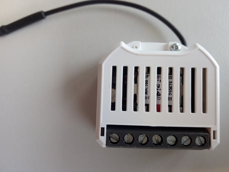
Product Image


1 - Heartbeat rate
If the notification System Heartbeat is on, a notification report System Heartbeat is sent periodically every 60 minutes (default value).Size: 2 bytes
Default: 60
Minimum: 1
Maximum: 1440
Possible values
| From | To | Desription |
|---|---|---|
| 1 | 1440 | Heartbeat Rate [min] |
2 - Main voltage
Together with the mesured current and the Phase shift configuration parameter the Main Voltage confirguation parameter is used to calculate the power of the outut.Size: 2 bytes
Default: 230
Minimum: 80
Maximum: 280
Possible values
| From | To | Desription |
|---|---|---|
| 80 | 280 | Main Voltage [V] |
3 - Phase shift - cosines phi
Together with the mesured current and the Main Voltage configuration parameter the Phase shift configruation parameter is used to calculate the power of the outut.Size: 2 bytes
Default: 100
Minimum: 0
Maximum: 100
Possible values
| From | To | Desription |
|---|---|---|
| 0 | 100 | Phase Shift [0.01] |
4 - Leading/trailing-edge
Output 1 is dimmable and the parameter is used for deciding on how to dimm the lighting device. The dimming can be achieved by using leading-edge (forward phase) dimming (parameter set to 0) or with trailing-edge (reverse phase) dimming (parameter set to 1).Size: 2 bytes
Default: 0
Minimum: 0
Maximum: 1
Possible values
| From | To | Desription |
|---|---|---|
| 0 | 0 | Leading Edge |
| 1 | 1 | Trailing Edge |
5 - Send interval energy, output 1
Period with which the energy of output 1 is sent by a Meter Report.Size: 2 bytes
Default: 5
Minimum: 1
Maximum: 120
Possible values
| From | To | Desription |
|---|---|---|
| 1 | 120 | Send interval energy [min] |
6 - Minimum delta energy send, output 1
When the energy of output 1 changes by this anount the energy value is sent by a Meter Report.Size: 2 bytes
Default: 2000
Minimum: 1
Maximum: 50000
Possible values
| From | To | Desription |
|---|---|---|
| 1 | 50000 | Minimum delta energy send [0.001 kWh] |
7 - Send interval power, output 1
Period with which the power of output 1 is sent by a Meter Report.Size: 2 bytes
Default: 5
Minimum: 1
Maximum: 120
Possible values
| From | To | Desription |
|---|---|---|
| 1 | 120 | Send interval power [min] |
8 - Minimum delta power, output 1
When the power of output 1 changes by this anount the energy value is sent by a Meter Report.Size: 2 bytes
Default: 5
Minimum: 1
Maximum: 100
Possible values
| From | To | Desription |
|---|---|---|
| 1 | 100 | Minimum delta power [%] |
1. Activate the “Add” ” mode on your controller. 2. Press a button connected to input I3 four times in quick succession to start include (“Add”). If a switch is used instead of the button, it must be changed accordingly eight times. 3. Alternatively you can press the small lever (T) four times in quick succession with an insulated pen to start “Add”. When the device is in the “Add” mode, the LED flashes green. When finished, the new status is: Add: The LED lights up briefly in green Remove: The LED lights up briefly in red
1. Activate the “Remove” mode on your controller. 2. Press a button connected to input I3 four times in quick succession to start exclude (“Remove”). If a switch is used instead of the button, it must be changed accordingly eight times. 3. Alternatively you can press the small lever (T) four times in quick succession with a insulated pen to start “Remove”. When the device is in the “Remove” mode, the LED flashes red. When finished, the new status is: Add: The LED lights up briefly in green Remove: The LED lights up briefly in red
Please use this procedure only when the network primary controller is missing or otherwise inoperable. Power-up the device and then press the small lever (T) for 10 seconds with an insulated pen. Reset: The LED lights up briefly in red
The QR code located on the side of the housing.
| Type | Value(s) |
|---|
| Group | Type |
|---|---|
| Power Management | Power status: Power has been applied |
| System | Heartbeat |
| Meter type |
|---|
| Electric Meter Consumption |