Aeotec
Smart Switch 7
ZWA023-A
Binary Switch
HW: 1 FW: 1.02
ZGM130
7.12.2
0x0371 (881)
0x0103 (259)
0x0017 (23)
ZC12-20050064
2020-05-21 10:18:14.340348
N/A
Enhanced 232 Slave
Always On Slave
Z-Wave Smart Switch 7
Aeotec Smart Switch 7 is a Z-Wave Switch plug-in module specifically used to enable Z-Wave command and control (on/off) of any plug-in tool. It can report immediate wattage consumption or kWh energy usage over a period of time. In the event of power failure, non-volatile memory retains all programmed information relating to the unit’s operating status. The Plug is also a security S2 Z-Wave device, it supports Over The Air (OTA) feature for the products firmware upgrade and SmartStart network pairing feature.
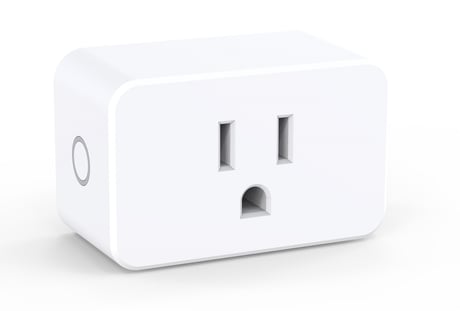
Product Image


1 - LED Setting
This parameter is used to change the reaction of LED setting. 0 - Disable LED completely. LED will only be used for network operation indicator, such as inclusion, exclusion, factory reset.Size: 1 byte
Default: 2
Minimum: 0
Maximum: 2
Possible values
| From | To | Desription |
|---|---|---|
| 0 | 0 | Disable LED completely |
| 1 | 0 | Turn on between particular times only (act as night light). |
| 2 | 0 | Display On/Off Status. |
2 - Night Light On Time
This parameter is used to configure the Night Light on time. User can use Color CC to change the Night Light color(default Red). Only useful when parameter 1 is set to 1. RR = Reserved HH = Hours MM = Minutes SS = Seconds Default = 0x00180000 means 6pmSize: 4 bytes
Default: 1572864
Minimum: 0
Maximum: 2316633
Possible values
| From | To | Desription |
|---|---|---|
| 0 | 2316633 | This parameter is used to configure the Night Light on time.RR = Reserved HH = Hours MM = Minutes SS = Seconds Default = 0x00180000 means 6pm |
3 - Night Light Off Time
This parameter is used to configure the Night Light off time. Only useful when parameter 1 is set to 1. RR = Reserved HH = Hours MM = Minutes SS = Seconds Default = 0x00060000 means 6amSize: 4 bytes
Default: 393216
Minimum: 0
Maximum: 2316633
Possible values
| From | To | Desription |
|---|---|---|
| 0 | 2316633 | This parameter is used to configure the Night Light off time. Only useful when parameter 1 is set to 1. RR = Reserved HH = Hours MM = Minutes SS = Seconds Default = 0x00060000 means 6am |
4 - LED Blink Duration
Set the duration of blink, unit second. 0 - indicates that it is not blinking 1~255 - set the durationSize: 1 byte
Default: 0
Minimum: 0
Maximum: 255
Possible values
| From | To | Desription |
|---|---|---|
| 0 | 0 | Indicates that it is not blinking |
| 1 | 255 | Set the duration |
5 - LED Blink Speed
Set amount of blinks per second. i.e. If set to 5, it should blink 5 times per second.Size: 1 byte
Default: 5
Minimum: 1
Maximum: 24
Possible values
| From | To | Desription |
|---|---|---|
| 1 | 24 | Set amount of blinks per second. |
6 - Send Alert When In Use
Send alert when in use. A Scene Activation Set command will be sent when energy draw is above this setting value. 0 - disable 1~3000 - enable, unit WSize: 2 bytes
Default: 100
Minimum: 0
Maximum: 3000
Possible values
| From | To | Desription |
|---|---|---|
| 0 | 0 | Disable |
| 1 | 3000 | Enable |
7 - Plug Always On
Prevents the plug from being turned off via its button. 0 - the plug will operate as normal and can be turned on or off. 1 - the button on the plug will be disabled for on and off commands, but still work for network inclusion and exclusion. 2 - the plug will ignore any commands to turn it off and it will ignore any use of the button (but still work for network inclusion and exclusion)Size: 1 byte
Default: 0
Minimum: 0
Maximum: 2
Possible values
| From | To | Desription |
|---|---|---|
| 0 | 0 | the plug will operate as normal and can be turned on or off. |
| 1 | 0 | the button on the plug will be disabled for on and off commands, but still work for network inclusion and exclusion. |
| 2 | 0 | the plug will ignore any commands to turn it off and it will ignore any use of the button (but still work for network inclusion and exclusion) |
8 - Power Out Action
Set the plug’s action in case of power out. 0 - last status 1 - power on 2 - power offSize: 1 byte
Default: 0
Minimum: 0
Maximum: 2
Possible values
| From | To | Desription |
|---|---|---|
| 0 | 0 | Last status |
| 1 | 1 | Power On |
| 2 | 2 | Power Off |
9 - Group3 Scene Id
Set the scene id when Scene Activation Set Command sent through group3. Refer parameter 6 for more information.Size: 1 byte
Default: 255
Minimum: 1
Maximum: 255
Possible values
| From | To | Desription |
|---|---|---|
| 1 | 255 | Set the scene id when Scene Activation Set Command sent through group3. |
10 - Over-load Protection
Turn off switch when current of load connected bypasses the maximum allowed power regardless of always on setting. Unit W. 0 - disable overload protection 1~1800 - When watt detected above this setting value, the switch will be turned off immediately. And an over-load notification will be sent.Size: 2 bytes
Default: 1800
Minimum: 0
Maximum: 1800
Possible values
| From | To | Desription |
|---|---|---|
| 0 | 0 | disable overload protection |
| 1 | 1800 | When watt detected above this setting value, the switch will be turned off immediately. And an over-load notification will be sent. |
11 - Over-voltage Protection
This parameter is used to set the over-voltage protect value, unit V. 0 - disable over-voltage protection 95~255 - When voltage detected above this setting value, the switch will be turned off immediately. And an over-voltage notification will be sent.Size: 1 byte
Default: 135
Minimum: 0
Maximum: 255
Possible values
| From | To | Desription |
|---|---|---|
| 0 | 0 | disable over-voltage protection |
| 1 | 255 | When voltage detected above this setting value, the switch will be turned off immediately. And an over-voltage notification will be sent. |
19 - Threshold Check Time
Set the period of threshold check. Unit second. 0 - disable all threshold settings 1~255 - set in seconds on how fast device checks for threshold settingsSize: 1 byte
Default: 5
Minimum: 0
Maximum: 255
Possible values
| From | To | Desription |
|---|---|---|
| 0 | 0 | disable all threshold settings |
| 1 | 255 | set in seconds on how fast device checks for threshold settings |
20 - kWh Report Threshold
Energy kWh threshold reporting enable/disable. Unit kWh.Size: 2 bytes
Default: 100
Minimum: 0
Maximum: 10000
Possible values
| From | To | Desription |
|---|---|---|
| 0 | 0 | Disable kWh threshold reporting |
| 1 | 10000 | kWh threshold setting. |
21 - Watt Report Threshold
Threshold setting for Watt for inducing automatic report.Unit W.Size: 2 bytes
Default: 0
Minimum: 0
Maximum: 2500
Possible values
| From | To | Desription |
|---|---|---|
| 0 | 0 | Disable Watt threshold reporting |
| 1 | 2500 | Watt threshold setting. |
22 - Current Report Threshold
Threshold settings for current for inducing automatic report. Unit ASize: 1 byte
Default: 0
Minimum: 0
Maximum: 150
Possible values
| From | To | Desription |
|---|---|---|
| 0 | 0 | Disable Watt threshold reporting |
| 1 | 150 | Current threshold setting. |
23 - Watt Automatic Report Time
Set the automatic report time of Watt. Unit second.Size: 2 bytes
Default: 600
Minimum: 0
Maximum: 65535
Possible values
| From | To | Desription |
|---|---|---|
| 0 | 65535 | Set the automatic report time of Watt |
24 - kWh Automatic Report Time
Set the automatic report time of kWh. Unit second.Size: 2 bytes
Default: 600
Minimum: 0
Maximum: 65535
Possible values
| From | To | Desription |
|---|---|---|
| 0 | 65535 | Set the automatic report time of kWh. Unit second. |
25 - Voltage Automatic Report Time
Set the automatic report time of Voltage. Unit second.Size: 2 bytes
Default: 600
Minimum: 0
Maximum: 65535
Possible values
| From | To | Desription |
|---|---|---|
| 0 | 65535 | Set the automatic report time of Voltage. Unit second. |
26 - Current Automatic Report Time
Set the automatic report time of Current. Unit second.Size: 2 bytes
Default: 600
Minimum: 0
Maximum: 65535
Possible values
| From | To | Desription |
|---|---|---|
| 0 | 65535 | Set the automatic report time of Current. Unit second. |
30 - Alarm Settings
Determines if alarms are enabled in Switch, and what Switch will react to which alarms.Size: 1 byte
Default: 0
Minimum: 0
Maximum: 255
Possible values
| From | To | Desription |
|---|---|---|
| 1 | 0 | Smoke Alarm |
| 2 | 0 | CO Alarm |
| 4 | 0 | CO2 Alarm |
| 8 | 0 | Heat Alarm |
| 16 | 0 | Water Alarm |
| 32 | 0 | Access Control |
| 64 | 0 | Home Security |
| 128 | 0 | Motion Sensor trigger |
| 0 | 0 | Disable alarm |
31 - Alarm Response
Enabled by Alarm Settings, and determines what the switch does in the case an alarm is triggered. 0 - disable , no reaction to alarm settings 1 - Switch is ON 2 - Switch is OFF 3~255 - Sets rate at which Switch turns ON and OFF in seconds. (i.e. If set to 3, then Switch will turn ON in 0.3 seconds, and then turn OFF in 0.3 seconds in a cycle until user disables the alarm manually. If set to 255, then it will cycle every 25.5 seconds)Size: 1 byte
Default: 0
Minimum: 0
Maximum: 255
Possible values
| From | To | Desription |
|---|---|---|
| 0 | 0 | disable , no reaction to alarm settings |
| 1 | 1 | Switch is ON |
| 2 | 2 | Switch is OF |
| 3 | 255 | Sets rate at which Switch turns ON and OFF in seconds. |
32 - Alarm Disable Setting
Determines the method of disabling the alarm of the device. 0 - Can be disabled by 1 tapping Switches action button once. 1 - Can be disabled by 2 tapping Switches action button within 1 second. 2 - Can be disabled by 4 tapping Switches action button within 2 seconds. 4 - Can be disabled by pressing and holding Switches action button about 4 seconds. 5~255 - Sets the duration of the alarm in seconds (i.e Sets this setting to 50, the alarm state of the switch will disable after 50 seconds)Size: 1 byte
Default: 1
Minimum: 0
Maximum: 255
Possible values
| From | To | Desription |
|---|---|---|
| 0 | 0 | Can be disabled by 1 tapping Switches action button once. |
| 1 | 1 | Can be disabled by 2 tapping Switches action button within 1 second. |
| 2 | 2 | Can be disabled by 4 tapping Switches action button within 2 seconds. |
| 4 | 4 | Can be disabled by pressing and holding Switches action button about 4 seconds. |
| 5 | 255 | Sets the duration of the alarm in seconds (i.e Sets this setting to 50, the alarm state of the switch will disable after 50 seconds) |
40 - Automatic Off Timer
Acts as auto off after as soon as the switch turns ON, setting is set in seconds. 0 - no auto off with timer 1~86400 - secondsSize: 4 bytes
Default: 0
Minimum: 0
Maximum: 86400
Possible values
| From | To | Desription |
|---|---|---|
| 0 | 0 | no auto off with timer |
| 1 | 86400 | seconds |
41 - Automatic On Timer
Acts as auto on after as soon as the switch turns OFF, setting is set in seconds. 0 - no auto on with timer 1~86400 - secondsSize: 4 bytes
Default: 0
Minimum: 0
Maximum: 86400
Possible values
| From | To | Desription |
|---|---|---|
| 0 | 0 | no auto on with timer |
| 1 | 86400 | Seconds |
42 - Report Command Setting
Which report will be sent to lifeline group when the output state is changed. 0 - Send nothing 1 - Send Basic Report 2 - Send Switch Binary ReportSize: 1 byte
Default: 2
Minimum: 0
Maximum: 2
Possible values
| From | To | Desription |
|---|---|---|
| 0 | 0 | Send nothing |
| 1 | 0 | Send Basic Report |
| 2 | 0 | Send Switch Binary Report |
255 - Factory Reset or Initialization
Restore the product to factory settings and remove from the network. 0x55555555 - Restore the product to factory settings and remove from the network. Other - Initialize all configuration parameters to default values.Size: 4 bytes
Default: 0
Minimum: 0
Maximum: 4294967295
Possible values
| From | To | Desription |
|---|---|---|
| 0 | 0 | Initialize all configuration parameters to default values. |
| 4294967295 | 4294967295 | Restore the product to factory settings and remove from the network |
Turn the gateway/ primary controller into inclusion mode, then short press the Action Button on the product one time.
Turn the gateway/ primary controller into exclusion mode, then short press the Action Button on the product 2 times.
Press and hold the Action Button for 15-20s. Note: Please use this procedure only when the network primary controller is missing or otherwise inoperable.
Page 2 in the User Manual,there is a schematic diagram indicating the location of the QR/DSK code.
| Group | Type |
|---|---|
| Power Management |
|
| Meter type |
|---|
| Electric Meter Consumption |