Everspring
Universal module with 3 In 3 Out
SA301-1
Notification Sensor
HW: 1 FW: 1.00:00.04
SD3502
6.81.06
0x0403 (1027)
0x0003 (3)
0x0007 (7)
ZC10-20056912
2020-05-05 12:41:18.60131
N/A
Enhanced 232 Slave
Always On Slave
Yes
SA301-1 Universal Module has 3 sets of signal input terminals and 3 sets of relay output terminals.
SA301-1 has 3 sets of input terminals and 3 sets of relay output. Through the Universal Module, the Z-Wave Controller can read the input signal from wired sensors and control the output of wired actuators. This product can be operated in any Z-Wave network with other Z-Wave certified devices from other manufactures. All mains operated nodes within the network will act as repeater regardless of vender to increase reliability of the network.
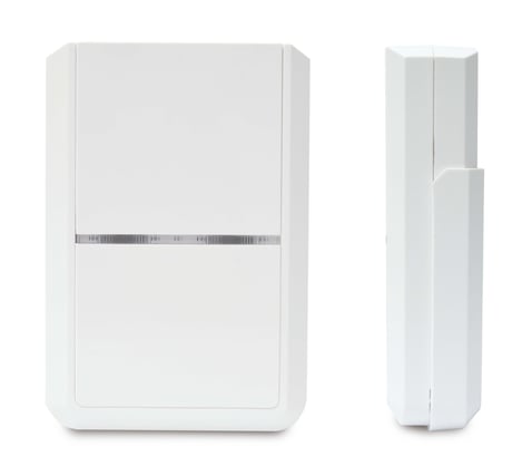
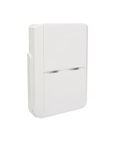
Product Image


1 - IN1 Mode
Size =1, Default Value = 0x40 Bit 7:Corresponds to values in Config 4, 5 - 0 = Trigger on when voltage under Low-threshold, Trigger off when over Hi-threshold - 1 = Trigger on when voltage over Hi-threshold, Trigger off when under Low-threshold Bit 6:IN1 3.3V pull-high On/Off , 0 = Off, 1 = On Bit 5-4 : Fixed at 0. Bit 3:1 = Activate OUT3 relay when IN1 trigger Bit 2:1 = Activate OUT2 relay when IN1 trigger Bit 1:1 = Activate OUT1 relay when IN1 trigger Bit 0:Fixed at 0.Size: 1 byte
Default: 64
Minimum: -128
Maximum: 127
Possible values
| From | To | Desription |
|---|---|---|
| -128 | 127 | Values From -128~127 will tell the device to active IN1 Mode |
2 - OUT1 relay Trigger ON time
Size =1, Default Value = 0x05 (500ms) Step of 100ms, ‘0’ = remain onSize: 1 byte
Default: 5
Minimum: -128
Maximum: 127
Possible values
| From | To | Desription |
|---|---|---|
| -128 | 127 | Relay 1 turn on period |
3 - Group 2 turn on time when triggered by IN1
Size =1, Default Value = 0xB4 (Off after 180 secs) Step of 1 sec, ‘0’ = remain onSize: 1 byte
Default: -76
Minimum: -128
Maximum: 127
Possible values
| From | To | Desription |
|---|---|---|
| -128 | 127 | Group 2 turn on period. |
4 - IN1 Hi-threshold Voltage Trigger Level
Size =1, Default Value = 0x19 (IN1 trigger off when over 2500mV). Step of 100mV.Size: 1 byte
Default: 25
Minimum: -128
Maximum: 127
Possible values
| From | To | Desription |
|---|---|---|
| -128 | 127 | High threshold voltage level for trigger on (or trigger off, depending on mode). |
5 - IN1 Low-threshold Voltage Trigger Level
Size =1 Default Value = 0xA (IN1 trigger on when under 1000mV)Size: 1 byte
Default: 10
Minimum: -128
Maximum: 127
Possible values
| From | To | Desription |
|---|---|---|
| -128 | 127 | Low threshold voltage level for trigger on (or trigger off, depending on mode). |
6 - IN2 Mode
Size =1, Default Value = 0x40 Bit 7:Corresponds to values in Config 9, 10 - 0 = Trigger on when voltage under Low-threshold, Trigger off when over Hi-threshold - 1 = Trigger on when voltage over Hi-threshold, Trigger off when under Low-threshold Bit 6:IN2 3.3V pull-high On/Off , 0 = Off, 1 = On Bit 5-4 : Fixed at 0. Bit 3:1 = Activate OUT3 relay when IN2 trigger Bit 2:1 = Activate OUT2 relay when IN2 trigger Bit 1:1 = Activate OUT1 relay when IN2 trigger Bit 0:Fixed at 0.Size: 1 byte
Default: 64
Minimum: -128
Maximum: 127
Possible values
| From | To | Desription |
|---|---|---|
| -128 | 127 | Values From -128~127 will tell the device to active IN2 Mode |
7 - OUT2 relay Trigger ON time
Size =1, Default Value = 0x05 (500ms) Step of 100ms, ‘0’ = remain onSize: 1 byte
Default: 5
Minimum: -128
Maximum: 127
Possible values
| From | To | Desription |
|---|---|---|
| -128 | 127 | Relay 2 turn on period |
8 - Group 3 turn on time when triggered by IN2
Size =1, Default Value = 0xB4 (Off after 180 secs) Step of 1 sec, ‘0’ = remain onSize: 1 byte
Default: -76
Minimum: -128
Maximum: 127
Possible values
| From | To | Desription |
|---|---|---|
| -128 | 127 | Group 3 turn on period. |
9 - IN2 Hi-threshold Voltage Trigger Level
Size =1, Default Value = 0x19 (IN2 trigger off when over 2500mV). Step of 100mV.Size: 1 byte
Default: 25
Minimum: -128
Maximum: 127
Possible values
| From | To | Desription |
|---|---|---|
| -128 | 127 | High threshold voltage level for trigger on (or trigger off, depending on mode). |
10 - IN2 Low-threshold Voltage Trigger Level
Size =1 Default Value = 0xA (IN2 trigger on when under 1000mV)Size: 1 byte
Default: 10
Minimum: -128
Maximum: 127
Possible values
| From | To | Desription |
|---|---|---|
| -128 | 127 | Low threshold voltage level for trigger on (or trigger off, depending on mode). |
11 - IN3 Mode
Size =1, Default Value = 0x40 Bit 7:Corresponds to values in Config 14, 15 - 0 = Trigger on when voltage under Low-threshold, Trigger off when over Hi-threshold - 1 = Trigger on when voltage over Hi-threshold, Trigger off when under Low-threshold Bit 6:IN3 3.3V pull-high On/Off , 0 = Off, 1 = On Bit 5-4 : Fixed at 0. Bit 3:1 = Activate OUT3 relay when IN3 trigger Bit 2:1 = Activate OUT2 relay when IN3 trigger Bit 1:1 = Activate OUT1 relay when IN3 trigger Bit 0:Fixed at 0.Size: 1 byte
Default: 64
Minimum: -128
Maximum: 127
Possible values
| From | To | Desription |
|---|---|---|
| -128 | 127 | Values From -128~127 will tell the device to active IN3 Mode |
12 - OUT3 relay Trigger ON time
Size =1, Default Value = 0x05 (500ms) Step of 100ms, ‘0’ = remain onSize: 1 byte
Default: 5
Minimum: -128
Maximum: 127
Possible values
| From | To | Desription |
|---|---|---|
| -128 | 127 | Relay 3 turn on period |
13 - Group 4 turn on time when triggered by IN3
Size =1, Default Value = 0xB4 (Off after 180 secs) Step of 1 sec, ‘0’ = remain onSize: 1 byte
Default: -76
Minimum: -128
Maximum: 127
Possible values
| From | To | Desription |
|---|---|---|
| -128 | 127 | Group 4 turn on period. |
14 - IN3 Hi-threshold Voltage Trigger Level
Size =1, Default Value = 0x19 (IN3 trigger off when over 2500mV). Step of 100mVSize: 1 byte
Default: 25
Minimum: -128
Maximum: 127
Possible values
| From | To | Desription |
|---|---|---|
| -128 | 127 | High threshold voltage level for trigger on (or trigger off, depending on mode). |
15 - IN3 Low-threshold Voltage Trigger Level
Size =1 Default Value = 0xA (IN3 trigger on when under 1000mV)Size: 1 byte
Default: 10
Minimum: -128
Maximum: 127
Possible values
| From | To | Desription |
|---|---|---|
| -128 | 127 | Low threshold voltage level for trigger on (or trigger off, depending on mode). |
16 - Auto Report Voltage time
Size =1, Default Value = 0x1E (30mins) Step= 1 min.Size: 1 byte
Default: 30
Minimum: -128
Maximum: 127
Possible values
| From | To | Desription |
|---|---|---|
| -128 | 127 | Periodic auto report for voltage input at IN1~3. |
17 - Tamper Mode
Size =1, Default Value = 0x00 Bit 3:1 = Activate OUT3 Relay when Tamper Bit 2:1 = Activate OUT2 Relay when Tamper Bit 1:1 = Activate OUT1 Relay when TamperSize: 1 byte
Default: 0
Minimum: 0
Maximum: 7
Possible values
| From | To | Desription |
|---|---|---|
| 0 | 7 | 0: No activate relay out; 1: Activate OUT1 Relay when Tamper; 2: Activate OUT2 Relay when Tamper; 3: Activate OUT1 & OUT2 Relay when Tamper; 4: Activate OUT3 Relay when Tamper; 5: Activate OUT1 & OUT3 Relay when Tamper; 6: Activate OUT2 & OUT3 Relay when Tamper; 7: Activate OUT1 & OUT2 & OUT3 Relay when Tamper |
18 - Set ARM/DISARM Input
Sets the ARM/DISARM informationSize: 1 byte
Default: 0
Minimum: 0
Maximum: 3
Possible values
| From | To | Desription |
|---|---|---|
| 0 | 3 | 0: No ARM/DISARM Input 1: IN 1 is ARM/DISARM Input 2: IN 2 is ARM/DISARM Input 3: IN 3 is ARM/DISARM Input |
1.Put the Z-Wave Controller into inclusion mode. 2.Press the Link button 3 times within 1.5 seconds to put the unit into inclusion mode.
1. Put the Z-Wave Controller into exclusion mode. 2. Press the Link button 3 times within 1.5 seconds to put the unit into exclusion mode.
1. Press the Link button 3 times within 1.5 seconds to put the unit into exclusion mode. 2. Within 1 second of step 1, press the Link button again and hold for 5 seconds. 3. Node ID is excluded. The unit reverts to factory default state. (This procedure should only be used when the controller is inoperable.)
Main features: 3 sets of input terminals, supporting dry contact or analog input Threshold level can be set for each input Notifies controller when input triggers 3 sets of relay output terminals, delivering NC/NO dry contact output* Output can be set to activate automatically when input terminals trigger Backup battery during power loss Notifies controller if power loss/recovers and when backup battery becomes low Tamper switch to detect removal from its mount Supports Z-Wave S2 security protocol with security-enabled Controller
If you are connecting this unit to a Z-Wave Controller that utilizes the S2 security protocol, you may be asked by your controller to enter a 5-digit PIN that is unique to each unit. This can be found in one of two places: - on the QR code label on the back of the unit - on the insert card inside the packaging.
| Type | Value(s) |
|---|
| Group | Type |
|---|---|
| Access Control |
|
| Home Security | Cover status: Tampering, product cover removed |
| Power Management |
|
| System | Cover status: Tampering, product cover removed |
| Sensor type |
|---|
| Voltage |