Q-light
Z-Wave Zerodim 2pol
1400441.0
Light Dimmer Switch
HW: 255 FW: 4.03
ZM5202
6.81.06
0x0433 (1075)
0x0003 (3)
0x000E (14)
ZC10-20056914
2020-05-27 13:34:56.801598
N/A
Enhanced 232 Slave
Always On Slave
Zerodim Z-Wave 2pol 2-180W LED load 0-99% dimming range
Zerodim Z-Wave 2pol by Q-light is a wireless smart home device. Features: - breaks both phases (L and N) - 0-99% dimming range - 2-180W LED load - Compatible with any Z-Wave or Z-Wave Plus Controller - There is memorized function at power off - OverLoad protection - Soft start function - SmartStart - This device is a security enable Z-Wave Plus product that is able to use encrypted Z-Wave Plus messages to communicate to other security enable Z-Wave Plus products.
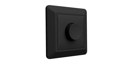
Product Image
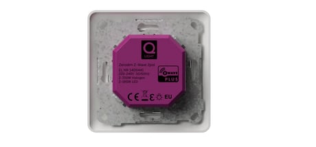
Zerodim Z-Wave 2pol back
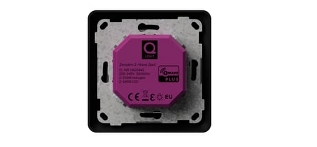
Zerodim Z-Wave 2pol side

Zerodim Z-Wave 2pol side

Zerodim Z-Wave 2pol white front
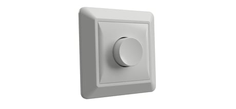
Zerodim Z-Wave 2pol black front


1 - Minimum brightness level
This parameter refers to the minimum brightness that the dimmer can achieve. This parameter cannot exceed the Maximum brightness level. The default value is 12.Size: 1 byte
Default: 12
Minimum: 1
Maximum: 98
Possible values
| From | To | Desription |
|---|---|---|
| 1 | 98 | Set the desired value from 1 to 98% for the minimum dim level that the dimmer is restricted to; the dimmer will not go lower than the value set here. |
2 - Maximum brightness level
This parameter refers to the maximum brightness that the dimmer can achieveSize: 1 byte
Default: 99
Minimum: 2
Maximum: 99
Possible values
| From | To | Desription |
|---|---|---|
| 2 | 99 | Set the desired value from 2 to 99% for the maximum dim level that the dimmer is restricted to; the dimmer will not go higher than the value set here. |
3 - Automatic control - dimming step size
This parameter defines the percentage value of dimming step during the automatic control.Size: 1 byte
Default: 1
Minimum: 1
Maximum: 99
Possible values
| From | To | Desription |
|---|---|---|
| 1 | 99 | Set the desired value from 1 to 99% for dim step size;The dimmer is dimmed up or down based on the percentage of the value set here for each step during the automatic control. |
4 - Automatic control - time of a dimming step
This parameter defines the time of single dimming step set in parameter 3 during the automatic control. Available settings:1-255(10ms-2.55s,in 10ms steps). Default value:1(10ms)Size: 2 bytes
Default: 1
Minimum: 1
Maximum: 255
Possible values
| From | To | Desription |
|---|---|---|
| 1 | 255 | Set the desired value from 1 to 255(10ms-2.55s,in 10ms steps) for the time of a dimming step. The amount of time the dimmer takes to adjust each step during the automatic control is the value set here. |
5 - Manual control - dimming step size
This parameter defines the percentage value of dimming step during the manual control.Size: 1 byte
Default: 1
Minimum: 1
Maximum: 99
Possible values
| From | To | Desription |
|---|---|---|
| 1 | 99 | Set the desired value from 1 to 99% for dim step size;The dimmer is dimmed up or down based on the percentage of the value set here for each step during the manual control. |
6 - Manual control - time of a dimming step
This parameter defines the time of single dimming step set in parameter 5 during the manual control. Available settings:1-255(10ms-2.55s,in 10ms steps). Default value:5(50ms)Size: 2 bytes
Default: 5
Minimum: 1
Maximum: 255
Possible values
| From | To | Desription |
|---|---|---|
| 1 | 255 | Set the desired value from 1 to 255(10ms-2.55s,in 10ms steps) for the time of a dimming step. The amount of time the dimmer takes to adjust each step during the manual control is the value set here. |
7 - Memory function after power failure
If this parameter is set to 1,the Device will restore its brightness before power failure.Size: 1 byte
Default: 1
Minimum: 0
Maximum: 1
Possible values
| From | To | Desription |
|---|---|---|
| 0 | 1 | Set the desired value from 0 to 1 to turn on/off the memory function.Setting this value to 0 turns off the dimmer's Memory fucntion.Setting this value to 1 truns on the dimmer's Memory function. |
8 - Scene ID set
Scene ID is set by this configuration. Note: The actual action of each SCENE ID are set by SCENE_ACTUATOR_CONF(0x26) command.Size: 2 bytes
Default: 1
Minimum: 1
Maximum: 255
Possible values
| From | To | Desription |
|---|---|---|
| 1 | 255 | Set the desired number from 1 to 255 as current scene ID.The dimmer will drive the load lamp based on the brightness stored in the scene ID set here,when the scene function is triggered.But the brightness value stored in each scene ID is set by the SCENE_ACTUATOR_CONF(0X26) command |
9 - Timer functionality (auto - off)
This parameter allows to automatically switch off the device after specified time from switching on the light source. It may be useful when the Zerodim Z-Wave is installed in the stairway. Available settings: 0 - Function disabled 1-32767 - time to turn off measured in seconds (1s-9.1h)Size: 2 bytes
Default: 0
Minimum: 0
Maximum: 32767
Possible values
| From | To | Desription |
|---|---|---|
| 0 | 32767 | Set the desired value from 0 to 32767(0--Function disable,1-32767--1s-32767s) fas the time at which the dimmer will automatically turn off.Setting this value to 0 will disable the dimmer's countdown function.Set this value to 1-32767 and the dimmer will turn off when the dimmer countdown reaches the set value. |
Classic Learn Mode: 1. Place the Zerodim Z-Wave 2pol within the direct range of your Z-Wave controller. 2. Identify switch rotary knob (turns the light on). 3. Set the main controller in (security/non-security) add mode (see the controller’s manual). 4. Quickly, three times press switch rotary knob. 5. Wait for the adding process to end. 6. Successful adding will be confirmed by the Z-Wave controller’s message.
Removing (Exclusion): Allowing to remove the Z-Wave device from existing Z-Wave network. 1. Place the Zerodim Z-Wave 2pol within the direct range of your Z-Wave controller. 2. Identify switch rotary knob (turns the light on) . 3. Set the main controller in (security/non-security) add mode (see the controller’s manual). 4. Quickly, three times press switch rotary knob. 5. Wait for the removing process to end.
Resetting the Z-Wave Puck: 1. Quickly, nine times press switch S1 / S2 or Internal button. 2. Wait for the resetting process to end, which is signaled with the LED indicator blinks 20 times. Device reset status: Turn on the light at maximum brightness. Please use this procedure only when the network primary controller is missing or otherwise inoperable
1.Association - Instructions_ZerodimZwave_2pol_English_A4,Page 2 2.Notification - Instructions_ZerodimZwave_2pol_English_A4,Page2 3.Advanced parameters - Instructions_ZerodimZwave_2pol_English_A4,Page 2
Security 2 DSK is located on the side of the product Instructions_ZerodimZwave_2pol_English_A4,Page 1
| Type | Value(s) |
|---|
| Group | Type |
|---|---|
| Heat Alarm | Heat sensor status: Overheat detected |
| Power Management | Over-load status: Over-load detected |