Fibar Group S.A.
WALLI CONTROLLER
FGWCEU-201
Central Scene Device
HW: 1 FW: 7.00
ZGM130
None
0x010F (271)
0x2301 (8961)
0x1000 (4096)
ZC12-20060078
2020-06-24 22:47:58.054593
N/A
Enhanced 232 Slave
Always On Slave
Yes
FIBARO Walli Controller is a smart wall-mounted Z-Wave remote controller that can activate scenes or control other Z-Wave devices via associations.
FIBARO Walli Controller is a smart wall-mounted Z-Wave remote controller that can activate scenes or control other Z-Wave devices via associations. Main features: • Can be used for controlling various types of Z-Wave devices, e.g. switches, dimmers, roller shutters. • Is a part of FIBARO Walli line of smart devices. • Pre-set configurations allow to easily adjust operation for specific type of controlled devices. • May be installed on a smooth surface or on a mounting box. • Can be powered using battery or VDC power supply. • Is equipped with a built-in temperature sensor. • Supports Z-Wave network Security Modes: S0 with AES-128 encryption and S2 Authenticated with PRNG-based encryption. • Works as a Z-Wave signal repeater when VDC powered.
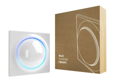
Product Image


13 - LED frame – brightness
This parameter allows to adjust the LED frame brightness.Size: 1 byte
Default: 100
Minimum: 0
Maximum: 100
Possible values
| From | To | Desription |
|---|---|---|
| 0 | 0 | LED disabled |
| 1 | 100 | 1-100% brightness |
20 - Operation mode
This parameter defines operation of the device. Choose the mode depending on the type of the device you want to control remotelySize: 1 byte
Default: 0
Minimum: 0
Maximum: 6
Possible values
| From | To | Desription |
|---|---|---|
| 0 | 0 | scene controller mode |
| 1 | 1 | double button mode |
| 2 | 2 | 3-position single button mode |
| 3 | 3 | switch controller mode |
| 4 | 4 | dimmer controller mode |
| 5 | 5 | roller shutter / gate controller mode (step-by-step) |
| 6 | 6 | venetian blinds controller mode (step-by-step) |
150 - LED ring – first button
This parameter defines the colour of first button indicator (upper part of the LED ring) for indications using Indicator CC.Size: 2 bytes
Default: 1
Minimum: 0
Maximum: 8
Possible values
| From | To | Desription |
|---|---|---|
| 0 | 0 | LED disabled |
| 1 | 1 | White |
| 2 | 2 | Red |
| 3 | 3 | Green |
| 4 | 4 | Blue |
| 5 | 5 | Yellow |
| 6 | 6 | Cyan |
| 7 | 7 | Magenta |
| 8 | 8 | LAPD (blinking red-white-blue) |
151 - LED ring – second button
This parameter defines the colour of second button indicator (lower part of the LED ring) for indications using Indicator CC.Size: 2 bytes
Default: 1
Minimum: 0
Maximum: 8
Possible values
| From | To | Desription |
|---|---|---|
| 1 | 1 | White |
| 2 | 2 | Red |
| 3 | 3 | Green |
| 4 | 4 | Blue |
| 5 | 5 | Yellow |
| 6 | 6 | Cyan |
| 7 | 7 | Magenta |
| 8 | 8 | LAPD (blinking red-white-blue) |
| 0 | 0 | LED disabled |
152 - 1st button - double click value
This parameter defines value of Basic Set or Multilevel Set frame (depending on selected mode) sent to associated devices after double click. This parameter is not relevant for Scene Controller Mode.Size: 2 bytes
Default: 99
Minimum: 0
Maximum: 255
Possible values
| From | To | Desription |
|---|---|---|
| 0 | 99 | value of Basic Set |
| 255 | 255 | Multilevel Set frame |
153 - 2nd button - double click value
This parameter defines value of Basic Set or Multilevel Set frame (depending on selected mode) sent to associated devices after double click. This parameter is not relevant for Scene Controller Mode.Size: 2 bytes
Default: 99
Minimum: 0
Maximum: 255
Possible values
| From | To | Desription |
|---|---|---|
| 0 | 99 | value of Basic Set |
| 255 | 255 | Multilevel Set frame |
1. Set the main controller in (Security/non-Security Mode) add mode (see the controller’s manual). 2. Quickly, three times click one of the buttons. 3. If you are adding in Security S2 Authenticated, input the underlined part of the DSK (label on the bottom of the box). 4. LED will start blinking yellow, wait for the adding process to end. 5. Adding result will be confirmed by the Z-Wave controller’s message and the LED frame: • Green – successful (non-secure, S0, S2 non-authenticated), • Magenta – successful (Security S2 Authenticated), • Red – not successful.
1. Set the main controller into remove mode (see the controller’s manual). 2. Quickly, three times click, then press and hold one of the buttons for 12 seconds. 3. Release the button when the device glows green. 4. Quickly click the button to confirm. 5. LED will start blinking yellow, wait for the removing process to end. 6. Successful removing will be confirmed by the Z-Wave controller’s message and red LED colour.
1. Quickly, three times click, then press and hold one of the buttons. 2. After 3 seconds LED ring signals adding status: • Blinking green – entering the menu (added as non-secure, S0, S2 non-authenticated) • Blinking magenta – entering the menu (added as Security S2 Authenticated) • Blinking red – entering the menu (not added to a Z-Wave network) 3. The LED ring will turn off for 3 seconds, then start signalling menu positions. 4. Release the button when device signals desired position with colour: • WHITE – wake up the device 5. Quickly click the button to confirm.
1. Quickly, three times click, then press and hold one of the buttons for 21 seconds. 2. Release the button when the device glows yellow. 3. Quickly click the button to confirm. 4. After a few seconds the device will be restarted, which is signalled with red LED colour.
If you are adding in Security S2 Authenticated, input the underlined part of the DSK (label on the bottom of the box).
The device will select the powering mode during adding to the Z-Wave network, prioritizing external power supply if connected. To change the mode after adding, you must change the installation accordingly, then remove and add the device again.
The capabilities of the device are changed at the level of adding the device to the network. So rediscover is not needed.
| Type | Value(s) |
|---|
| Sensor type |
|---|
| Air Temperature |