LUX
KONOse Senior Care Smart Hub Thermostat
KN-ZW-SE1-20
Thermostat - HVAC
HW: 2 FW: 1.00:00.224
ZM5202
6.71.03
0x0411 (1041)
0x0001 (1)
0x2112 (8466)
ZC10-20066923
2020-06-17 23:20:25.856329
N/A
Enhanced 232 Slave
Always On Slave
KONOse is a smart thermostat made for Seniors
KONOse is a smart thermostat made for Seniors. It seamlessly connects to many smart hubs and blends in or stands out with its interchangeable Décor-snap covers™. KONOse is designed for energy savings, ease of use, increased visibility and for those with limited fine motor skills. System • Modes: Heat, Cool, Heat & Cool • Conventional: Forced air, gas, oil & electric furnaces (up to 2h/1c) • Heat Pumps: With or without Aux/Emergency heat • Hydronic (hot water) zone valves (2 wire) • Power: 4 AA alkaline batteries , C-wire or LUX Power Bridge (sold separately)
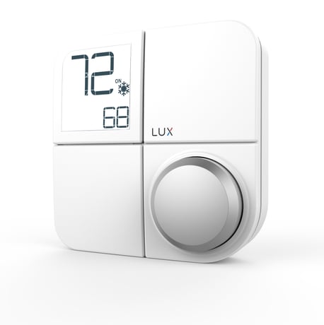
Product Image


1 - User Temperature Calibration
User Temperature CalibrationSize: 2 bytes
Default: 0
Minimum: -450
Maximum: 450
Possible values
| From | To | Desription |
|---|---|---|
| -450 | 450 | step-size = 10, in steps of 0.1°F |
2 - Temperature Unit (C/F)
Temperature Unit (C/F)Size: 1 byte
Default: 1
Minimum: 0
Maximum: 1
Possible values
| From | To | Desription |
|---|---|---|
| 0 | 0 | C |
| 1 | 1 | F |
3 - Available Control mode
Available Control modeSize: 1 byte
Default: 0
Minimum: 0
Maximum: 4
Possible values
| From | To | Desription |
|---|---|---|
| 0 | 0 | Heat and Cool, Auto |
| 1 | 1 | Heat Only |
| 2 | 2 | Cool Only |
| 3 | 3 | Heat and Cool, no Auto |
| 4 | 4 | reserved |
4 - System Type
System TypeSize: 1 byte
Default: 0
Minimum: 0
Maximum: 4
Possible values
| From | To | Desription |
|---|---|---|
| 0 | 0 | Furnace Gas |
| 1 | 1 | Furnace Electric |
| 2 | 2 | Heat Pump |
| 3 | 3 | Boiler no fan |
| 4 | 4 | reserved |
5 - Reversal valve Type in Heat Pump
Reversal valve Type in Heat PumpSize: 1 byte
Default: 0
Minimum: 0
Maximum: 1
Possible values
| From | To | Desription |
|---|---|---|
| 0 | 0 | O-valve |
| 1 | 1 | B-valve |
8 - Temperature Limit - Heat Max
Temperature Limit - Heat Max (F)Size: 2 bytes
Default: 90
Minimum: 60
Maximum: 90
Possible values
| From | To | Desription |
|---|---|---|
| 60 | 90 | Heat Max (F) |
9 - Temperature Limit - Heat Min
Temperature Limit - Heat Min (F)Size: 2 bytes
Default: 45
Minimum: 45
Maximum: 60
Possible values
| From | To | Desription |
|---|---|---|
| 45 | 60 | Heat Min (F) |
10 - Temperature Limit - Cool Max
Temperature Limit - Cool Max (F)Size: 2 bytes
Default: 95
Minimum: 60
Maximum: 95
Possible values
| From | To | Desription |
|---|---|---|
| 60 | 95 | Cool Max (F) |
11 - Temperature Limit - Cool Min
Temperature Limit - Cool Min (F)Size: 2 bytes
Default: 50
Minimum: 50
Maximum: 75
Possible values
| From | To | Desription |
|---|---|---|
| 50 | 75 | Cool Min (F) |
12 - Temperature Minimum Setpoint Deadband
Temperature Minimum Setpoint Deadband (in a step of 0.1F)Size: 2 bytes
Default: 200
Minimum: 200
Maximum: 500
Possible values
| From | To | Desription |
|---|---|---|
| 200 | 500 | step-size = 10 |
13 - Enable / Disable Emergency heat option in mode menu
Enable / Disable Emergency heat option in mode menu. Note: for Heat Pump system only.Size: 1 byte
Default: 1
Minimum: 0
Maximum: 1
Possible values
| From | To | Desription |
|---|---|---|
| 0 | 0 | disable |
| 0 | 1 | enable |
14 - Ambient Temperature Change Step-size
Ambient Temperature Change Step-size. 0.5F – 4F range with a step-size of 0.5F (0.25C).Size: 2 bytes
Default: 50
Minimum: 50
Maximum: 400
Possible values
| From | To | Desription |
|---|---|---|
| 50 | 50 | 0.5F (0.25C) |
| 100 | 100 | 1.0F (0.50C) |
| 150 | 150 | 1.5F (0.75C) |
| 200 | 200 | 2.0F (1.00C) |
| 250 | 250 | 2.5F (1.25C) |
| 300 | 300 | 3.0F (1.50C) |
| 350 | 350 | 3.5F (1.75C) |
| 400 | 400 | 4.0F (2.00C) |
15 - Regular Ambient Temperature Reporting Interval
Regular Ambient Temperature Reporting IntervalSize: 1 byte
Default: 4
Minimum: 1
Maximum: 24
Possible values
| From | To | Desription |
|---|---|---|
| 1 | 24 | 1 - 24 hours |
16 - Regular Operating State Reporting Interval
Regular Operating State Reporting IntervalSize: 1 byte
Default: 4
Minimum: 1
Maximum: 24
Possible values
| From | To | Desription |
|---|---|---|
| 1 | 24 | 1 - 24 hours |
17 - Command Echo
Command Echo for - Thermostat Mode - Thermostat Fan mode - Thermostat SetpointSize: 1 byte
Default: 1
Minimum: 0
Maximum: 1
Possible values
| From | To | Desription |
|---|---|---|
| 0 | 0 | disable |
| 1 | 1 | enable |
1. Initiate inclusion on your home control system using the instructions provided with it 2. In HOME screen, press and hold the knob for 5 seconds to enter the main menu 3. Rotate the knob to select the RF icon , then press the knob to enter the inclusion/exclusion menu 4. In the inclusion/exclusion menu, select ADD and press the knob to confirm 5. The device will begin the adding process – you will see this screen: - Step 1: Device prepares to add to the hub - Step 2: At the hub portal, click “Add device”. Noted: If the hub is supporting S2 (authenticated) security mode, it will ask the user to provide the DSK code of the device to complete the inclusion process. The DSK code is printed on the product label. Input the first 5 digits in the hub portal and follow the instructions provided by the hub. Remove the décor snap cover from the device and the product label is attached on the device front housing. If S0 or S2 (unauthenticated) is used, no DSK is needed then. - Step 3: Device is added to the hub successfully.
1. In HOME screen, press and hold the knob for 5 seconds to enter the main menu 2. Rotate the knob to select the RF icon , then press the knob to enter the inclusion/exclusion menu 3. In the inclusion/exclusion menu, select RST and press the knob to confirm 4. The device will begin the removal process – you will see this screen: - Step 1: Device prepares to be removed from the hub: - Step 2: At the hub portal, click “Remove device”. - Step 3: Device is removed from the hub successfully.
Rotate knob or send command from hub.
Factory Reset Note: Please use this procedure only when the network primary controller is missing or otherwise inoperable. 1. Enter the installer setting menu and select the installer option #99, then press the knob to confirm. 2. All the device parameters will be restored to factory default. The Z-Wave network setting will also be erased. User must perform the device inclusion with their hub / gateway again to re-establish the network.
The DSK can be found in the product label underneath the decor cover of the product.
| Type | Value(s) |
|---|
| Group | Type |
|---|---|
| Power Management | Battery maintenance status: Replace battery now |
| Sensor type |
|---|
| Air Temperature |