HELTUN
High Load Switch
HE-HLS01
Binary Switch
HW: 82 FW: 1.01
ZGM130
7.11.1
0x0344 (836)
0x0004 (4)
0x000A (10)
ZC12-20070081
2020-07-07 16:18:34.778052
N/A
Enhanced 232 Slave
Always On Slave
Advanced Programmable Z-Wave Plus v2 In-Wall High Load Switch on the Z-Wave 700 platform. With 16 Amp load capacity, it is a perfect addition to any circuit breaker panel. Fits easily behind outlets or switches in standard electrical junction boxes. It can also provide Internet-connected thermostat functions where a local display and controls are not needed.
The HELTUN HE-HLS01 is an advanced programmable Z-Wave Plus v2 in-wall high load switch that controls many devices, such as electrical outlets & panels, electric water heaters, radiators, fireplaces, and radiant floor or de-icing systems. It can also provide Internet-connected thermostat functions where a local display and controls are not needed. HELTUN HE-HLS01 fits easily behind outlets or switches in standard electrical junction boxes. Features: • 16A maximum load • 10 scenarios for output control • 6 thermostat operating modes • 4 association groups • External NTC sensor • Real time energy consumption meter • Onboard Real Time Clock (RTC) • 8 safety functions & notifications • Works both with VAC 85-265 and VDC 24-48 • Incorporates HELTUN Advanced Zero-Cross Technology The HELTUN HE-HLS01 is part of an entire line of smart, connected products designed to provide the best technology has to offer without compromising stylish living. Learn more about HELTUN products at www.heltun.com
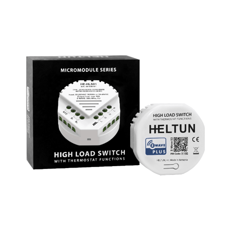
Product Image
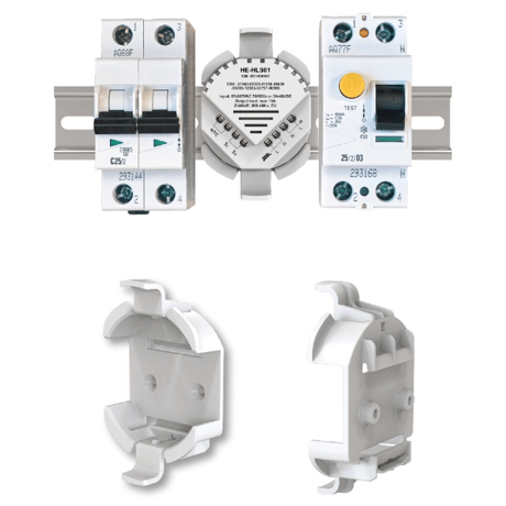
On a Din Rail
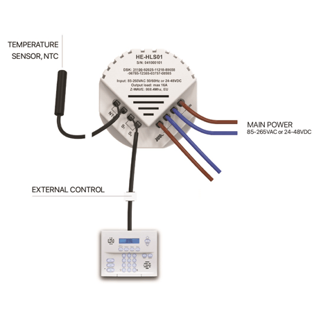
Control Inputs
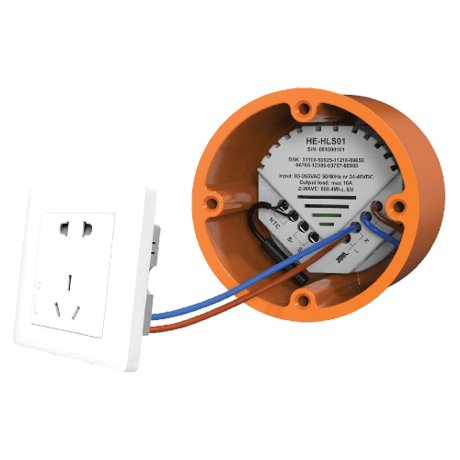
Installation
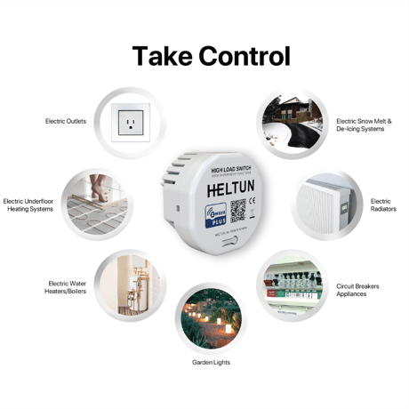
Use Cases
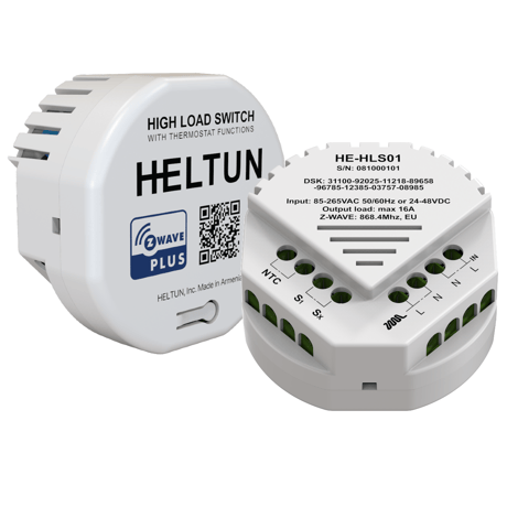
Back&Front
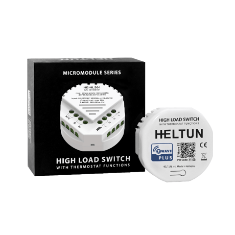


1 - DEVICE TYPE
Device Type. This parameter is read only and indicates in which mode the device is included. The device can be included either in the Binary Switch mode or in the Thermostat mode. Use inclusion in Binary Switch mode if there is a need to control on/off device and use inclusion in Thermostat mode if there is a need to control heating system. For the appropriate inclusion process see the section Z-Wave Network of manual.Size: 1 byte
Default: 0
Minimum: 0
Maximum: 1
Possible values
| From | To | Desription |
|---|---|---|
| 0 | 0 | Parameter is read only. |
| 1 | 0 | Parameter is read only. |
2 - FREQUENCY REGION
Frequency Region. The HLS01 has Z-Wave 700 platform chip inside which allows to use the device in different Z-Wave frequencies. If there is a need to use the device in the frequency different from the factory default change the value of this parameter according to the list is user manual.Size: 1 byte
Default: 0
Minimum: 0
Maximum: 9
Possible values
| From | To | Desription |
|---|---|---|
| 0 | 9 | Select the corresponding region frequency |
3 - OUTPUT MODE
Output NO/NC Mode. The device can operate in Normal Open (NO) mode and in Normal Close (NC) mode.Size: 1 byte
Default: 0
Minimum: 0
Maximum: 1
Possible values
| From | To | Desription |
|---|---|---|
| 0 | 0 | The device switch operates in NO mode and there is no voltage on output when the device is in OFF state. The output will be powered when device goes to ON state. |
| 1 | 0 | The output will be powered in OFF state and will be no voltage on output when the device is in ON state. |
4 - TIME CORRECTION
Time correction by controllerSize: 1 byte
Default: 1
Minimum: 0
Maximum: 1
Possible values
| From | To | Desription |
|---|---|---|
| 0 | 0 | Switch off auto-correction |
| 1 | 0 | If the device is connected to a Z-Wave gateway, the time and day will be periodically polled and corrected from the gateway |
5 - WEEKDAY
Week day. Allows manually adjustment of the day of the week in case the HE-HLS01 is not connected to any Z-Wave gateway or the Parameter 04 (auto-correction) is set to 0.Size: 1 byte
Default: 1
Minimum: 1
Maximum: 7
Possible values
| From | To | Desription |
|---|---|---|
| 1 | 0 | Monday |
| 2 | 0 | Tuesday |
| 3 | 0 | Wednesday |
| 4 | 0 | Thursday |
| 5 | 0 | Friday |
| 6 | 0 | Saturday |
| 7 | 0 | Sunday |
6 - HOUR
Time hour. Allows manually adjustment of hours for internal clock in case the HE-HLS01 is not connected to any Z-Wave gateway or the Parameter 04 (auto-correction) is set to 0.Size: 1 byte
Default: 0
Minimum: 0
Maximum: 23
Possible values
| From | To | Desription |
|---|---|---|
| 0 | 23 | This Parameter allows manual adjustment of Time in hours (24 hours). |
7 - MINUTE
Time minutes. Allows manually adjustment of minutes for internal clock in case the HE-HLS01 is not connected to any Z-Wave gateway or the Parameter 04 (auto-correction) is set to 0.Size: 1 byte
Default: 0
Minimum: 0
Maximum: 59
Possible values
| From | To | Desription |
|---|---|---|
| 0 | 59 | This Parameter allows manual adjustment of the Time in minutes (60 minutes)) |
8 - NTC RESISTANCE
External NTC Temperature Sensor Resistance (kΩ)Size: 1 byte
Default: 10
Minimum: 1
Maximum: 100
Possible values
| From | To | Desription |
|---|---|---|
| 1 | 100 | Floor Sensor Resistance in kiloOhms (kΩ) |
9 - TEMPERATURE SENSOR OFFSET
Temperature Calibration in °C, x10. Temperature Sensor Calibration This Parameter defines the offset value for external NTC temperature sensor. If the temperature sensor is not calibrated properly, manual calibration can be made by adjusting the values up to ±10.0°C or ±18°F.Size: 1 byte
Default: 0
Minimum: -100
Maximum: 100
Possible values
| From | To | Desription |
|---|---|---|
| -100 | 100 | This value will be added or subtracted from the temperature sensor reading |
10 - TEMPERATURE SCALE MODE
Temperature Scale Mode. This parameter determines in which unit of measurement (degrees Celsius or Fahrenheit) the device will report the temperature, and also determines the scale that will be interpreted by the configuration parameters. Note: This configuration parameter has impact on configuration parameters 9,12,16,17 and 32, 42-69 in thermostat mode. If scale is set to degrees Fahrenheit, configuration values at mentioned parameters will be automatically converted from Celsius to Fahrenheit and any change in the values will be interpreted as Fahrenheits.Size: 1 byte
Default: 0
Minimum: 0
Maximum: 1
Possible values
| From | To | Desription |
|---|---|---|
| 0 | 0 | Celsius |
| 1 | 0 | Fahrenheit |
11 - TEMPERATURE REPORT INTERVAL
Temperature Sensor Consecutive Report Interval. This Parameter defines the interval between consecutive reports of temperature sensor reading to the gateway. Note: If the sensor readings change, the device will send the report to the gateway regardless of this parameter value. In order not to increase traffic on your network, it is not recommended to reduce the value of this parameter. We recommend reducing the value of this parameter only in case of poor connection, when reports from the device does not always reach the gateway.Size: 1 byte
Default: 10
Minimum: 1
Maximum: 120
Possible values
| From | To | Desription |
|---|---|---|
| 1 | 120 | The value can be adjusted from 1 to 120 minutes |
12 - TEMPERATURE REPORT THRESHOLD
Temperature Sensor Report Threshold. This parameter determines the change in temperature level resulting in temperature sensors report being sent to the gateway. In Celsius scale mode the value of this parameter should be x10, e.g. for 0.4°C use value 4. From 1 (0.1°C) to 100 (10°C) can be selected in Celsius scale mode and from 1 to 18 can be selected in Fahrenheit scale mode. The factory default value is 5 (0.5°) in °C scale and 1 in °F scale.Size: 1 byte
Default: 5
Minimum: 0
Maximum: 100
Possible values
| From | To | Desription |
|---|---|---|
| 0 | 0 | Stop sending the reports |
| 1 | 100 | The change in temperature level resulting in temperature sensors report being sent to the gateway. |
13 - METER REPORT INTERVAL
Energy Consumption Meter Consecutive Report Interval. When the device is connected to the Z-Wave gateway (controller), it periodically sends to the gateway reports from its external temperature sensor and energy consumption meter even if there are not changes in the values. This Parameter defines the interval between consecutive reports of real time and cumulative energy consumption data to the gateway. Note: If the sensor readings change, the device will send the report to the gateway regardless of this parameter value. In order not to increase traffic on your network, it is not recommended to reduce the value of this parameter. We recommend reducing the value of this parameter only in case of poor connection, when reports from the device does not always reach the gateway. Note: Energy consumption meter function is available only if the device is AC powered.Size: 1 byte
Default: 10
Minimum: 1
Maximum: 120
Possible values
| From | To | Desription |
|---|---|---|
| 1 | 120 | The value can be adjusted from 1 to 120 minutes. |
14 - METER REPORT THRESHOLD
Energy Consumption Meter Report Threshold. This parameter determines how much the cumulative or real time energy consumption data need to increase/reduce to be reported to the gateway. The value of this parameter is in % and from 1 to 90 can be selected. Note: Energy consumption meter function is available only if the device is AC powered.Size: 1 byte
Default: 25
Minimum: 0
Maximum: 90
Possible values
| From | To | Desription |
|---|---|---|
| 0 | 0 | Stop sending the reports |
| 1 | 90 | The percentage (%) change in ambient illumination that results in cumulative or real time energy consumption data being sent to the gateway. |
15 - SYSTEM ERROR NOTIFICATION
Device Failure Notifications. If the HLS01 does not work properly it sends “System Failure” notification to the gateway with the error code. Errors code list (sent with the notification): 0 – No Error (no issue is detected) 1 – Relay Off Error (when unable to switch Off the relay output). 2 – Relay On Error (when unable to switch On the relay output). 3 – Relay On & Off Error (when unable to switch On and Off the relay output). 4 – NTC Error (when no NTC sensor is detected or when it is damaged). 5 – NTC and Relay Off Error (when no NTC sensor is detected or when it is damaged and unable to switch Off the relay output). 6 – NTC and Relay On Error (when no NTC sensor is detected or when it is damaged and unable to switch On the relay output). 7 – NTC and Relay On & Off Error (when no NTC sensor is detected or when it is damaged and unable to switch On and Off the relay output).Size: 1 byte
Default: 1
Minimum: 0
Maximum: 1
Possible values
| From | To | Desription |
|---|---|---|
| 0 | 0 | Disable “System Failure” notification |
| 1 | 0 | Ennable “System Failure” notification |
16 - TEMPERATURE RISE NOTIFICATION
Temperature Rise Notification. Use this parameter if you want to know about temperature rise before it reaches the critical value, defined in the “Overheat Protection” parameter. The device will send “Rapid Temperature Rise” notification to the gateway if the temperature sensor reading reaches the value defined in this parameter. The factory default value is 50 in °C scale and 122 in °F scale. Note: We recommend setting the value of this Parameter lower than value of Parameter 17 (Overheat Protection).Size: 2 bytes
Default: 50
Minimum: 0
Maximum: 248
Possible values
| From | To | Desription |
|---|---|---|
| 0 | 0 | Disable the notification |
| 1 | 248 | The value can be set from 1 to 120 in °C scale mode or from 32 to 248 in °F scale mode. |
17 - OVERHEAT PROTECTION LEVEL
Overheat Protection & Notification. You can define the maximum limit of temperature, reaching which the device will automatically switch Off the load and send “Overheat Detected” notification to the gateway. The factory default value is 60 in °C scale and 140 in °F scale.Size: 2 bytes
Default: 60
Minimum: 0
Maximum: 248
Possible values
| From | To | Desription |
|---|---|---|
| 0 | 0 | Disable the functionality |
| 1 | 248 | The value of this parameter can be set from 1 to 120 in °C scale mode or from 32 to 248 in °F scale mode. |
18 - OVERCURRENT NOTIFICATION
Over-Current Protection & Notification. The maximum load for the device is 16A. If the connected load current exceeds 16A the device will automatically switch Off the output and send the “Over-Current Detected” notification to the gateway. Note: Even if you turn off the notification, the device will switch Off the load when the current reaches 16A. Note: The protection works only if the device is AC powered.Size: 1 byte
Default: 1
Minimum: 0
Maximum: 1
Possible values
| From | To | Desription |
|---|---|---|
| 0 | 0 | Disable sending the notification |
| 1 | 0 | Enable sending the notification |
19 - OVERLOAD PROTECTION LEVEL
Over-Load Protection & Notification. You can define the maximum power in Watt for connected load. The device will automatically switch off the output and send “Over-Load Detected” notification to the gateway if power consumed by the connected load exceeds this limit. Note: The protection works only if the device is AC powered.Size: 2 bytes
Default: 3500
Minimum: 0
Maximum: 4000
Possible values
| From | To | Desription |
|---|---|---|
| 0 | 0 | Disable the functionality |
| 100 | 4000 | Maximum power in Watt for connected load |
20 - OVERVOLTAGE PROTECTION LEVEL
Over-Voltage Protection & Notification. The device constantly monitors the voltage of your electricity network. You can define the maximum voltage of network exceeding which the device will automatically switch off the output and send “Over-Voltage Detected” notification to the gateway. The value of this parameter can be set from 120 to 280 in volts. Note: The protection works only if the device is AC powered.Size: 2 bytes
Default: 240
Minimum: 0
Maximum: 280
Possible values
| From | To | Desription |
|---|---|---|
| 0 | 0 | Disable the functionality |
| 120 | 280 | Maximum voltage of network exceeding which the device will automatically switch off the output and send “Over-Voltage Detected” notification to the gateway. |
21 - VOLTAGE DROP PROTECTION LEVEL
Voltage Drop Protection & Notification. You can define the minimum voltage of your electricity network. If the voltage of the network drops determined level the device will automatically switch off the output and send “Voltage Drop Detected” notification to the gateway. Note: The protection works only if the device is AC powered.Size: 2 bytes
Default: 200
Minimum: 0
Maximum: 240
Possible values
| From | To | Desription |
|---|---|---|
| 0 | 0 | Disable the functionality |
| 80 | 240 | Minimum voltage of your electricity network. |
22 - SPARK PROTECTION
Sparks Protection & Notification. If connected load fails it can create sparks that may cause a fire. The device constantly monitors the power consumption of connected load and can detect even a small surge in consumption and automatically switch off the output and send “Surge Detected” notification to the gateway. Note: The protection works only if the device is AC powered.Size: 1 byte
Default: 1
Minimum: 0
Maximum: 1
Possible values
| From | To | Desription |
|---|---|---|
| 0 | 0 | Disable Sparks Protection & Notification |
| 1 | 0 | Enable Sparks Protection & Notification |
23 - RESERVED
Parameters from 23 to 30 are reserved by the manufacturer. Setting this parameter will have no impact on DUT functionality.Size: 4 bytes
Default: 0
Minimum: 0
Maximum: 4294967295
Possible values
| From | To | Desription |
|---|---|---|
| 0 | 4294967295 | Parameter reserved by the manufacturer. Setting this parameter will have no impact on DUT functionality. |
31 - LOAD ERROR NOTIFICATION
Parameter only for 'Thermostat' device type: Load Error Notification. The device can send the “Load Error” notification to the gateway when the relay is On but there is no power consumption (meaning possible problems with the heating system). Note: The function works only if the device is AC powered.Size: 1 byte
Default: 0
Minimum: 0
Maximum: 1
Possible values
| From | To | Desription |
|---|---|---|
| 0 | 0 | Disable sending the notification |
| 1 | 0 | Disable sending the notification |
32 - TEMPERATURE REGULATION HYSTERESYS
Parameter only for 'Thermostat' device type: Temperature Hysteresis. This Parameter defines the hysteresis value for temperature control. The HE-HLS01 will stabilize the temperature with selected hysteresis. For example, if the SET POINT is set for 25°C and HYSTERESIS is set for 0.5°C the HE-HLS01 will change the state to IDLE when the temperature reaches 25.0°C, but it will change the state to HEATING if the temperature drops lower than 24.5°C. The hysteresis can be changed from 0.2°C to 10.0°C range in Celsius mode, and from 1°F to 18.0°F in Fahrenheit mode.Size: 1 byte
Default: 5
Minimum: 2
Maximum: 100
Possible values
| From | To | Desription |
|---|---|---|
| 2 | 100 | Hysteresis value for temperature control. |
33 - BASIC SET MODE
Parameter only for 'Thermostat' device type: Basic Set Action This Parameter defines which Operating Mode the HE-HLS01 reverts to if the Basic Set command is received. If the Basic Set command value is 0 (OFF state) the HE-HLS01 will go to Manual mode and switch Off the heating element (IDLE mode). If the Basic Set command is value is 0xFF (ON state) the HE-HLS01 will change the Mode to the corresponding Parameter value.Size: 1 byte
Default: 1
Minimum: 1
Maximum: 5
Possible values
| From | To | Desription |
|---|---|---|
| 1 | 0 | HEAT mode |
| 2 | 0 | AUTO mode |
| 3 | 0 | DRY mode |
| 4 | 0 | ECO mode |
| 5 | 0 | VAC mode |
34 - S1 INPUT MODE
Parameter only for 'Thermostat' device type: S1 external input modeSize: 1 byte
Default: 0
Minimum: 0
Maximum: 3
Possible values
| From | To | Desription |
|---|---|---|
| 0 | 0 | The input state changes will be ignored by the Thermostat logic |
| 1 | 0 | The external input will operate in “Toggle Switch” mode: if the external input is shorted (with Sx or Line) the Thermostat switches to the operating mode selected in the Parameter 35 and switches to OFF mode when the external input is open. |
| 2 | 0 | The external input will operate in “Toggle Switch Reverse” mode: if the external input is shorted the Thermostat switches to OFF mode and switches to the operating mode selected in the Parameter 35 when the input is open. |
| 3 | 0 | The external input will operate in “Push Button (Momentary Switch)” mode: each press of button (shorten of input) will consistently change the mode to the operating mode selected in the Parameter 35. |
35 - S1 INPUT ACTION
Parameter only for 'Thermostat' device type: Mode number for S1 external input actionSize: 1 byte
Default: 1
Minimum: 1
Maximum: 5
Possible values
| From | To | Desription |
|---|---|---|
| 1 | 0 | HEAT mode |
| 2 | 0 | AUTO mode |
| 3 | 0 | DRY mode |
| 4 | 0 | ECO mode |
| 5 | 0 | VAC mode |
36 - DRY TIME
Parameter only for 'Thermostat' device type: Dry Mode Timeout. By choosing Dry Mode, the device will increase the temperature to the selected Set Point and keep it for the time specified in this parameter. As the Dry Time passes, the Thermostat will automatically change to the Mode set in the Parameter 37.Size: 2 bytes
Default: 30
Minimum: 1
Maximum: 720
Possible values
| From | To | Desription |
|---|---|---|
| 1 | 720 | A time range of 1 to 720 minutes (12 hours) can be set. |
37 - DRY MODE SWITCH
Parameter only for 'Thermostat' device type: Mode to switch after Dry mode operation completionSize: 1 byte
Default: 1
Minimum: 1
Maximum: 6
Possible values
| From | To | Desription |
|---|---|---|
| 1 | 0 | HEAT mode |
| 2 | 0 | AUTO mode |
| 4 | 0 | ECO mode |
| 5 | 0 | VAC mode |
| 6 | 0 | OFF mode |
38 - MORNING START TIME
Parameter only for 'Thermostat' device type: Morning start time. Format: HHMM. e.g.08:00 should be sent as 0800Size: 2 bytes
Default: 600
Minimum: 0
Maximum: 2359
Possible values
| From | To | Desription |
|---|---|---|
| 0 | 2359 | Morning start time. Format: HHMM (from 00:00 to 23:59) |
39 - DAY START TIME
Parameter only for 'Thermostat' device type: Day start time. Format: HHMM.Size: 2 bytes
Default: 900
Minimum: 0
Maximum: 2359
Possible values
| From | To | Desription |
|---|---|---|
| 0 | 2359 | Day start time. Format: HHMM (from 00:00 to 23:59) |
40 - EVENING START TIME
Parameter only for 'Thermostat' device type: Evening start time. Format: HHMM.Size: 2 bytes
Default: 1800
Minimum: 0
Maximum: 2359
Possible values
| From | To | Desription |
|---|---|---|
| 0 | 2359 | Evening start time. Format: HHMM (from 00:00 to 23:59) |
41 - NIGHT START TIME
Parameter only for 'Thermostat' device type: Night start time. Format: HHMM.Size: 2 bytes
Default: 2300
Minimum: 0
Maximum: 2359
Possible values
| From | To | Desription |
|---|---|---|
| 0 | 2359 | Night start time. Format: HHMM (from 00:00 to 23:59) |
42 - MONDAY MORNING TEMP
Parameter only for 'Thermostat' device type: Monday Morning temperature, valueX10Size: 2 bytes
Default: 240
Minimum: 10
Maximum: 1100
Possible values
| From | To | Desription |
|---|---|---|
| 10 | 1100 | Monday Morning temperature value |
43 - MONDAY DAYTIME TEMP
Parameter only for 'Thermostat' device type: Monday Day temperature, valueX10Size: 2 bytes
Default: 200
Minimum: 10
Maximum: 1100
Possible values
| From | To | Desription |
|---|---|---|
| 10 | 1100 | Monday Day temperature value |
44 - MONDAY EVENING TEMP
Parameter only for 'Thermostat' device type: Monday Evening temperature, valueX10Size: 2 bytes
Default: 230
Minimum: 10
Maximum: 1100
Possible values
| From | To | Desription |
|---|---|---|
| 10 | 1100 | Monday Evening temperature value |
45 - MONDAY NIGHT TEMP
Parameter only for 'Thermostat' device type: Monday Night temperature, valueX10Size: 2 bytes
Default: 180
Minimum: 10
Maximum: 1100
Possible values
| From | To | Desription |
|---|---|---|
| 10 | 1100 | Monday Night temperature value |
46 - TUESDAY MORNING TEMP
Parameter only for 'Thermostat' device type: Tuesday Morning temperature, valueX10Size: 2 bytes
Default: 240
Minimum: 10
Maximum: 1100
Possible values
| From | To | Desription |
|---|---|---|
| 10 | 1100 | Tuesday Morning temperature value |
47 - TUESDAY DAYTIME TEMP
Parameter only for 'Thermostat' device type: Tuesday Day temperature, valueX10Size: 2 bytes
Default: 200
Minimum: 10
Maximum: 1100
Possible values
| From | To | Desription |
|---|---|---|
| 10 | 1100 | Tuesday Day temperature value |
48 - TUESDAY EVENING TEMP
Parameter only for 'Thermostat' device type: Tuesday Evening temperature, valueX10Size: 2 bytes
Default: 230
Minimum: 10
Maximum: 1100
Possible values
| From | To | Desription |
|---|---|---|
| 10 | 1100 | Tuesday Evening temperature value |
49 - TUESDAY NIGHT TEMP
Parameter only for 'Thermostat' device type: Tuesday Night temperature, valueX10Size: 2 bytes
Default: 180
Minimum: 10
Maximum: 1100
Possible values
| From | To | Desription |
|---|---|---|
| 10 | 1100 | Tuesday Night temperature value |
50 - WEDNESDAY MORNING TEMP
Parameter only for 'Thermostat' device type: Wednesday Morning temperature, valueX10Size: 2 bytes
Default: 240
Minimum: 10
Maximum: 1100
Possible values
| From | To | Desription |
|---|---|---|
| 10 | 1100 | Wednesday Morning temperature value |
51 - WEDNESDAY DAYTIME TEMP
Parameter only for 'Thermostat' device type: Wednesday Day temperature, valueX10Size: 2 bytes
Default: 200
Minimum: 10
Maximum: 1100
Possible values
| From | To | Desription |
|---|---|---|
| 10 | 1100 | Wednesday Day temperature value |
52 - WEDNESDAY EVENING TEMP
Parameter only for 'Thermostat' device type: Wednesday Evening temperature, valueX10Size: 2 bytes
Default: 230
Minimum: 10
Maximum: 1100
Possible values
| From | To | Desription |
|---|---|---|
| 10 | 1100 | Wednesday Evening temperature value |
53 - WEDNESDAY NIGHT TEMP
Parameter only for 'Thermostat' device type: Wednesday Night temperature, valueX10Size: 2 bytes
Default: 180
Minimum: 10
Maximum: 1100
Possible values
| From | To | Desription |
|---|---|---|
| 10 | 1100 | Wednesday Night temperature value |
54 - THURSDAY MORNING TEMP
Parameter only for 'Thermostat' device type: Thursday Morning temperature, valueX10Size: 2 bytes
Default: 240
Minimum: 10
Maximum: 1100
Possible values
| From | To | Desription |
|---|---|---|
| 10 | 1100 | Thursday Morning temperature value |
55 - THURSDAY DAYTIME TEMP
Parameter only for 'Thermostat' device type: Thursday Day temperature, valueX10Size: 2 bytes
Default: 200
Minimum: 10
Maximum: 1100
Possible values
| From | To | Desription |
|---|---|---|
| 10 | 1100 | Thursday Day temperature value |
56 - THURSDAY EVENING TEMP
Parameter only for 'Thermostat' device type: Thursday Evening temperature, valueX10Size: 2 bytes
Default: 230
Minimum: 10
Maximum: 1100
Possible values
| From | To | Desription |
|---|---|---|
| 10 | 1100 | Thursday Evening temperature value |
57 - THURSDAY NIGHT TEMP
Parameter only for 'Thermostat' device type: Thursday Night temperature, valueX10Size: 2 bytes
Default: 180
Minimum: 10
Maximum: 1100
Possible values
| From | To | Desription |
|---|---|---|
| 10 | 1100 | Thursday Night temperature value |
58 - FRIDAY MORNING TEMP
Parameter only for 'Thermostat' device type: Friday Morning temperature, valueX10Size: 2 bytes
Default: 240
Minimum: 10
Maximum: 1100
Possible values
| From | To | Desription |
|---|---|---|
| 10 | 1100 | Friday Morning temperature value |
59 - FRIDAY DAYTIME TEMP
Parameter only for 'Thermostat' device type: Friday Day temperature, valueX10Size: 2 bytes
Default: 200
Minimum: 10
Maximum: 1100
Possible values
| From | To | Desription |
|---|---|---|
| 10 | 1100 | Friday Day temperature value |
60 - FRIDAY EVENING TEMP
Parameter only for 'Thermostat' device type: Friday Evening temperature, valueX10Size: 2 bytes
Default: 230
Minimum: 10
Maximum: 1100
Possible values
| From | To | Desription |
|---|---|---|
| 10 | 1100 | Friday Evening temperature value |
61 - FRIDAY NIGHT TEMP
Parameter only for 'Thermostat' device type: Friday Night temperature, valueX10Size: 2 bytes
Default: 180
Minimum: 10
Maximum: 1100
Possible values
| From | To | Desription |
|---|---|---|
| 10 | 1100 | Friday Night temperature value |
62 - SATURDAY MORNING TEMP
Parameter only for 'Thermostat' device type: Saturday Morning temperature, valueX10Size: 2 bytes
Default: 240
Minimum: 10
Maximum: 1100
Possible values
| From | To | Desription |
|---|---|---|
| 10 | 1100 | Saturday Morning temperature value |
63 - SATURDAY DAYTIME TEMP
Parameter only for 'Thermostat' device type: Saturday Day temperature, valueX10Size: 2 bytes
Default: 200
Minimum: 10
Maximum: 1100
Possible values
| From | To | Desription |
|---|---|---|
| 10 | 1100 | Saturday Day temperature value |
64 - SATURDAY EVENING TEMP
Parameter only for 'Thermostat' device type: Saturday Evening temperature, valueX10Size: 2 bytes
Default: 230
Minimum: 10
Maximum: 1100
Possible values
| From | To | Desription |
|---|---|---|
| 10 | 1100 | Saturday Evening temperature value |
65 - SATURDAY NIGHT TEMP
Parameter only for 'Thermostat' device type: Saturday Night temperature, valueX10Size: 2 bytes
Default: 180
Minimum: 10
Maximum: 1100
Possible values
| From | To | Desription |
|---|---|---|
| 10 | 1100 | Saturday Night temperature value |
66 - SUNDAY MORNING TEMP
Parameter only for 'Thermostat' device type: Sunday Morning temperature, valueX10Size: 2 bytes
Default: 240
Minimum: 10
Maximum: 1100
Possible values
| From | To | Desription |
|---|---|---|
| 10 | 1100 | Sunday Morning temperature value |
67 - SUNDAY DAYTIME TEMP
Parameter only for 'Thermostat' device type: Sunday Day temperature, valueX10Size: 2 bytes
Default: 200
Minimum: 10
Maximum: 1100
Possible values
| From | To | Desription |
|---|---|---|
| 10 | 1100 | Sunday Day temperature value |
68 - SUNDAY EVENING TEMP
Parameter only for 'Thermostat' device type: Sunday Evening temperature, valueX10Size: 2 bytes
Default: 230
Minimum: 10
Maximum: 1100
Possible values
| From | To | Desription |
|---|---|---|
| 10 | 1100 | Sunday Evening temperature value |
69 - SUNDAY NIGHT TEMP
Parameter only for 'Thermostat' device type: Sunday Night temperature, valueX10Size: 2 bytes
Default: 180
Minimum: 10
Maximum: 1100
Possible values
| From | To | Desription |
|---|---|---|
| 10 | 1100 | Sunday Night temperature value |
70 - RESERVED
For 'Thermostat' device type the parameters from 70 to 80 are reserved by the manufacturer. Setting this parameters will have no impact on DUT functionality.Size: 4 bytes
Default: 0
Minimum: 0
Maximum: 4294967295
Possible values
| From | To | Desription |
|---|---|---|
| 0 | 4294967295 | Parameter reserved by the manufacturer. Setting this parameter will have no impact on DUT functionality. |
131 - LOAD ON NOTIFICATION
The actual parameter number is 31 when the device is in the 'Binary Switch' mode. Load Switched On Notification. If this function is enabled the device will send “AC Mains Re-Connected” notification to the gateway each time when the relay output state changes to On. Note: This function can be useful for informing in case of automatic control of the load by schedule or scenario.Size: 1 byte
Default: 0
Minimum: 0
Maximum: 1
Possible values
| From | To | Desription |
|---|---|---|
| 0 | 0 | Disable sending the notification |
| 1 | 0 | Enable sending the notification |
132 - LOAD OFF NOTIFICATION
The actual parameter number is 32 when the device is in the 'Binary Switch' mode. Load Switched Off Notification. If this function is enabled the device will send “AC Mains Disconnected” notification to the gateway each time when the relay output state changes to Off. Note: This function can be useful for informing when the device automatically switches the output Off because of emergency case or in case of automatic control of the load by schedule or scenario.Size: 1 byte
Default: 1
Minimum: 0
Maximum: 1
Possible values
| From | To | Desription |
|---|---|---|
| 0 | 0 | Disable sending the notification |
| 1 | 0 | Enable sending the notification |
133 - TIME LIMITITED LOAD
The actual parameter number is 33 when the device is in the 'Binary Switch' mode. High Load Timeout Protection: Power Threshold If the HLS01 is used to control an electric socket, you can configure the device so that it automatically switch Off the socket if the potentially dangerous high load is connected longer than allowable time (time to be set in the Parameter 34), for example, if you left the iron switched On for too long. Set in this parameter the threshold value in watts, reaching which the connected load will be considered high. Note: If the connected load power is less than value of this parameter, the protection will not be activated. Note: If the Parameter 34 (time threshold) value is set to 0, the protection will not be activated. Note: The time counter is reset every time when the load consumption drops to zero. Note: We recommend activating the Load Switched Off notification (the Parameter 32) to be informed when the device automatically switch Off the socket. Note: The protection works only if the device is AC powered.Size: 2 bytes
Default: 0
Minimum: 0
Maximum: 3500
Possible values
| From | To | Desription |
|---|---|---|
| 0 | 0 | Disable the functionality |
| 100 | 3500 | The load limit in watts to automatically switch Off the socket |
134 - HIGH LOAD ON TIME LIMIT
The actual parameter number is 34 when the device is in the 'Binary Switch' mode. High Load Timeout Protection: Time Threshold If High Load Timeout Protection is activated (the Parameter 33 is set) use this parameter to set the threshold value in minutes. If the load is connected longer than this value, the device will automatically switch Off the socket. Note: If the value of this parameter is set 0, the protection will not be activated. Note: If the connected load power is less than value of the Parameter 33, the protection will not be activated. Note: The time counter is reset every time when the load consumption drops to zero. If the connected load may change its consumption, make sure that the time threshold will be reached before the load consumption drops. Note: We recommend activating the Load Switched Off notification (the Parameter 32) to be informed when the device automatically switch Off the socket. Note: The protection works only if the device is AC powered.Size: 2 bytes
Default: 0
Minimum: 0
Maximum: 1440
Possible values
| From | To | Desription |
|---|---|---|
| 0 | 0 | Disable the functionality |
| 1 | 1440 | If the load is connected longer than this value, the device will automatically switch Off the socket. |
135 - LOAD AUTO ON/OFF
The actual parameter number is 35 when the device is in the 'Binary Switch' mode. Load Switched On Notification. Auto On/Off If this function is enabled the device will switch Off the relay output when there is no consumption and switch On the output again when the load is reconnected. It is possible to set the delay for Auto Off function (in the Parameter 36) and for Auto On function (in the Parameter 37). Note: If the output is manually switched Off (from Gateway or External Input toggle) Auto ON function will be blocked until the output switches back to ON manually or the load disconnected. Note: The function works only if the device is AC powered.Size: 1 byte
Default: 0
Minimum: 0
Maximum: 1
Possible values
| From | To | Desription |
|---|---|---|
| 0 | 0 | Disable the functionality |
| 1 | 0 | Enable the functionality |
136 - AUTO OFF TIMEOUT
The actual parameter number is 36 when the device is in the 'Binary Switch' mode. Load Switched On Notification. Auto Off Timeout If Auto On/Off function (the Parameter 35) is enabled, it is possible to delay the Auto Off function. The output will be switched Off when there is no consumption for the interval defined in this parameter in minutes. Note: The function works only if the device is AC powered.Size: 1 byte
Default: 5
Minimum: 0
Maximum: 120
Possible values
| From | To | Desription |
|---|---|---|
| 0 | 0 | Switch Off the output immediately when consumption drops to 0W |
| 1 | 120 | Minutes after which the output will be switched Off when there is no consumption |
137 - AUTO ON RECONNECT TIMEOUT
The actual parameter number is 37 when the device is in the 'Binary Switch' mode. Load Switched On Notification. Auto On Reconnect Timeout If Auto On/Off function (the Parameter 35) is enabled, it is possible to delay the Auto On function. When the load is reconnected the relay output will be switched On after the time defined in this parameter in minutes. Note: The function works only if the device is AC powered.Size: 1 byte
Default: 0
Minimum: 0
Maximum: 120
Possible values
| From | To | Desription |
|---|---|---|
| 0 | 0 | Switch On the output immediately when the load is reconnected. |
| 1 | 120 | When the load is reconnected the relay output will be switched On after the time defined in this parameter in minutes. |
138 - S1 INPUT HOLD CONTROL MODE
The actual parameter number is 38 when the device is in the 'Binary Switch' mode. Load Switched On Notification.Size: 1 byte
Default: 2
Minimum: 0
Maximum: 3
Possible values
| From | To | Desription |
|---|---|---|
| 0 | 0 | Hold function is disabled |
| 1 | 0 | Operate like click (the Parameter 39) |
| 2 | 0 | Momentary Switch: When the button on switch connected to external input is held, (key closed) the relay output state is ON, as soon as the button is released (key opened) the relay output state changes to OFF. |
| 3 | 0 | Reversed Momentary Switch: When the button on switch connected to external input is held, the relay output state is OFF, as soon as the button is released the relay output state changes to ON. |
139 - S1 INPUT CLICK CONTROL MODE
The actual parameter number is 39 when the device is in the 'Binary Switch' mode. External Input: Click Control Mode.Size: 1 byte
Default: 1
Minimum: 0
Maximum: 5
Possible values
| From | To | Desription |
|---|---|---|
| 0 | 0 | Click function disabled |
| 1 | 0 | Toggle switch: relay inverts state (ON to OFF, OFF to ON). |
| 2 | 0 | Relay switches to ON state only |
| 3 | 0 | Relay switches to OFF state only |
| 4 | 0 | Timer: On>Off Mode: Relay output switches to ON state (contacts are closed) then after a specified time switches back to OFF state (contacts are open). The time is specified in the Parameter 40. |
| 5 | 0 | Timer: OFF>ON Mode: Relay output switches to OFF state (contacts are open) then after a specified time switches back to ON state (contacts are closed). The time is specified in Parameter 40. |
140 - RELAY TIMER DURATION
The actual parameter number is 40 when the device is in the 'Binary Switch' mode. Relay Timer Mode Duration These parameters specify the duration in seconds for the Timer mode (values 4 or 5 in the Parameter 39). Press the button on the switch connected to external input and the relay output goes to ON/OFF for the specified time then changes back to OFF/ON. Note: If the parameter value is set to “0” the relay output will operate as a short contact (duration is about 0.5 sec).Size: 2 bytes
Default: 0
Minimum: 0
Maximum: 43200
Possible values
| From | To | Desription |
|---|---|---|
| 0 | 43200 | The time value can be configured from 0 sec to 43200 sec (12 hours). |
141 - RELAY CONTROL SCENARIO 1
The actual parameter number is 41 when the device is in the 'Binary Switch' mode. Relay 1 Control by Scenario In these parameters, the relay state changes depending on day and time. For these configurations, parameter values are encoded as 7-digit numbers (ABCDEFG). A: State. 0 = Disabled, 1 = Enabled B: Day of week 0 = every day 1-7 = corresponding day (1 is Monday, 7 is Sunday) 8 = every weekday (Monday - Friday) 9 = every weekend (Saturday and Sunday) C: Change state to 0 = Switch OFF 1 = Switch ON DEFG: Time DE represents Hour (from 0 to 23), FG represents Minutes (from 0 to 59).Size: 4 bytes
Default: 0
Minimum: 0
Maximum: 1912359
Possible values
| From | To | Desription |
|---|---|---|
| 0 | 0 | Disable the functionality |
| 1000000 | 1912359 | Relay 1 Control Scenario |
142 - RELAY CONTROL SCENARIO 2
The actual parameter number is 42 when the device is in the 'Binary Switch' mode. Relay 2 Control by Scenario In these parameters, the relay state changes depending on day and time. For these configurations, parameter values are encoded as 7-digit numbers (ABCDEFG). A: State. 0 = Disabled, 1 = Enabled B: Day of week 0 = every day 1-7 = corresponding day (1 is Monday, 7 is Sunday) 8 = every weekday (Monday - Friday) 9 = every weekend (Saturday and Sunday) C: Change state to 0 = Switch OFF 1 = Switch ON DEFG: Time DE represents Hour (from 0 to 23), FG represents Minutes (from 0 to 59).Size: 4 bytes
Default: 0
Minimum: 0
Maximum: 1912359
Possible values
| From | To | Desription |
|---|---|---|
| 0 | 0 | Disable the functionality |
| 1000000 | 1912359 | Relay 2 Control Scenario |
143 - RELAY CONTROL SCENARIO 3
The actual parameter number is 43 when the device is in the 'Binary Switch' mode. Relay 3 Control by Scenario In these parameters, the relay state changes depending on day and time. For these configurations, parameter values are encoded as 7-digit numbers (ABCDEFG). A: State. 0 = Disabled, 1 = Enabled B: Day of week 0 = every day 1-7 = corresponding day (1 is Monday, 7 is Sunday) 8 = every weekday (Monday - Friday) 9 = every weekend (Saturday and Sunday) C: Change state to 0 = Switch OFF 1 = Switch ON DEFG: Time DE represents Hour (from 0 to 23), FG represents Minutes (from 0 to 59).Size: 4 bytes
Default: 0
Minimum: 0
Maximum: 1912359
Possible values
| From | To | Desription |
|---|---|---|
| 0 | 0 | Disable the functionality |
| 1000000 | 1912359 | Relay 3 Control Scenario |
144 - RELAY CONTROL SCENARIO 4
The actual parameter number is 44 when the device is in the 'Binary Switch' mode. Relay 4 Control by Scenario In these parameters, the relay state changes depending on day and time. For these configurations, parameter values are encoded as 7-digit numbers (ABCDEFG). A: State. 0 = Disabled, 1 = Enabled B: Day of week 0 = every day 1-7 = corresponding day (1 is Monday, 7 is Sunday) 8 = every weekday (Monday - Friday) 9 = every weekend (Saturday and Sunday) C: Change state to 0 = Switch OFF 1 = Switch ON DEFG: Time DE represents Hour (from 0 to 23), FG represents Minutes (from 0 to 59).Size: 4 bytes
Default: 0
Minimum: 0
Maximum: 1912359
Possible values
| From | To | Desription |
|---|---|---|
| 0 | 0 | Disable the functionality |
| 1000000 | 1912359 | Relay 4 Control Scenario |
145 - RELAY CONTROL SCENARIO 5
The actual parameter number is 45 when the device is in the 'Binary Switch' mode. Relay 5 Control by Scenario In these parameters, the relay state changes depending on day and time. For these configurations, parameter values are encoded as 7-digit numbers (ABCDEFG). A: State. 0 = Disabled, 1 = Enabled B: Day of week 0 = every day 1-7 = corresponding day (1 is Monday, 7 is Sunday) 8 = every weekday (Monday - Friday) 9 = every weekend (Saturday and Sunday) C: Change state to 0 = Switch OFF 1 = Switch ON DEFG: Time DE represents Hour (from 0 to 23), FG represents Minutes (from 0 to 59).Size: 4 bytes
Default: 0
Minimum: 0
Maximum: 1912359
Possible values
| From | To | Desription |
|---|---|---|
| 0 | 0 | Disable the functionality |
| 1000000 | 1912359 | Relay 5 Control Scenario |
146 - RELAY CONTROL SCENARIO 6
The actual parameter number is 46 when the device is in the 'Binary Switch' mode. Relay 6 Control by Scenario In these parameters, the relay state changes depending on day and time. For these configurations, parameter values are encoded as 7-digit numbers (ABCDEFG). A: State. 0 = Disabled, 1 = Enabled B: Day of week 0 = every day 1-7 = corresponding day (1 is Monday, 7 is Sunday) 8 = every weekday (Monday - Friday) 9 = every weekend (Saturday and Sunday) C: Change state to 0 = Switch OFF 1 = Switch ON DEFG: Time DE represents Hour (from 0 to 23), FG represents Minutes (from 0 to 59).Size: 4 bytes
Default: 0
Minimum: 0
Maximum: 1912359
Possible values
| From | To | Desription |
|---|---|---|
| 0 | 0 | Disable the functionality |
| 1000000 | 1912359 | Relay 6 Control Scenario |
147 - RELAY CONTROL SCENARIO 7
The actual parameter number is 47 when the device is in the 'Binary Switch' mode. Relay 7 Control by Scenario In these parameters, the relay state changes depending on day and time. For these configurations, parameter values are encoded as 7-digit numbers (ABCDEFG). A: State. 0 = Disabled, 1 = Enabled B: Day of week 0 = every day 1-7 = corresponding day (1 is Monday, 7 is Sunday) 8 = every weekday (Monday - Friday) 9 = every weekend (Saturday and Sunday) C: Change state to 0 = Switch OFF 1 = Switch ON DEFG: Time DE represents Hour (from 0 to 23), FG represents Minutes (from 0 to 59).Size: 4 bytes
Default: 0
Minimum: 0
Maximum: 1912359
Possible values
| From | To | Desription |
|---|---|---|
| 0 | 0 | Disable the functionality |
| 1000000 | 1912359 | Relay 7 Control Scenario |
148 - RELAY CONTROL SCENARIO 8
The actual parameter number is 48 when the device is in the 'Binary Switch' mode. Relay 8 Control by Scenario In these parameters, the relay state changes depending on day and time. For these configurations, parameter values are encoded as 7-digit numbers (ABCDEFG). A: State. 0 = Disabled, 1 = Enabled B: Day of week 0 = every day 1-7 = corresponding day (1 is Monday, 7 is Sunday) 8 = every weekday (Monday - Friday) 9 = every weekend (Saturday and Sunday) C: Change state to 0 = Switch OFF 1 = Switch ON DEFG: Time DE represents Hour (from 0 to 23), FG represents Minutes (from 0 to 59).Size: 4 bytes
Default: 0
Minimum: 0
Maximum: 1912359
Possible values
| From | To | Desription |
|---|---|---|
| 0 | 0 | Disable the functionality |
| 1000000 | 1912359 | Relay 8 Control Scenario |
149 - RELAY CONTROL SCENARIO 9
The actual parameter number is 49 when the device is in the 'Binary Switch' mode. Relay 9 Control by Scenario In these parameters, the relay state changes depending on day and time. For these configurations, parameter values are encoded as 7-digit numbers (ABCDEFG). A: State. 0 = Disabled, 1 = Enabled B: Day of week 0 = every day 1-7 = corresponding day (1 is Monday, 7 is Sunday) 8 = every weekday (Monday - Friday) 9 = every weekend (Saturday and Sunday) C: Change state to 0 = Switch OFF 1 = Switch ON DEFG: Time DE represents Hour (from 0 to 23), FG represents Minutes (from 0 to 59).Size: 4 bytes
Default: 0
Minimum: 0
Maximum: 1912359
Possible values
| From | To | Desription |
|---|---|---|
| 0 | 0 | Disable the functionality |
| 1000000 | 1912359 | Relay 9 Control Scenario |
150 - RELAY CONTROL SCENARIO 10
The actual parameter number is 50 when the device is in the 'Binary Switch' mode. Relay 10 Control by Scenario In these parameters, the relay state changes depending on day and time. For these configurations, parameter values are encoded as 7-digit numbers (ABCDEFG). A: State. 0 = Disabled, 1 = Enabled B: Day of week 0 = every day 1-7 = corresponding day (1 is Monday, 7 is Sunday) 8 = every weekday (Monday - Friday) 9 = every weekend (Saturday and Sunday) C: Change state to 0 = Switch OFF 1 = Switch ON DEFG: Time DE represents Hour (from 0 to 23), FG represents Minutes (from 0 to 59).Size: 4 bytes
Default: 0
Minimum: 0
Maximum: 1912359
Possible values
| From | To | Desription |
|---|---|---|
| 0 | 0 | Disable the functionality |
| 1000000 | 1912359 | Relay 10 Control Scenario |
151 - RESERVED
The actual parameter number is 51 when the device is in the 'Binary Switch' mode. For 'Binary Switch' device type the parameters from 51 to 60 are reserved by the manufacturer. Setting this parameters will have no impact on DUT functionality.Size: 4 bytes
Default: 0
Minimum: 0
Maximum: 4294967295
Possible values
| From | To | Desription |
|---|---|---|
| 0 | 42 | Parameter reserved by the manufacturer. Setting this parameter will have no impact on DUT functionality. |
To add the HE-HLS01 to an existing Z-Wave network (i.e. “inclusion”), do the following: 1. Ensure the HE-HLS01 is Powered On and the LED indicator blinks red slowly (i.e. it is excluded). 2. Start the Inclusion Mode from the gateway/controller. 3. To start the inclusion process on the HE-HLS01: a) if you want to use the device as a “Binary Switch”, double-press the service button on the device (with no more than a one-second interval between presses). b) if you want to use the device as a “Thermostat”, press four times the service button on the device (with no more than a one-second interval between presses). 4. The LED indicator will blink green quickly. 5. If the inclusion has been successful, the LED indicator will turn green for three seconds then continue slowly blinking green continuously while the HE-HLS01 is Powered On. 6. If the inclusion was not successful, the LED indicator will turn red for three seconds then continue slowly blinking red continuously while the HE-HLS01 is Powered On. In that case repeat the inclusion process (2-5) above.
To remove the HE-HLS01 from a Z-Wave network (i.e. “Exclusion”), do the following: 1. Ensure the HE-HLS01 is Powered On and the LED indicator blinks green slowly (i.e. it is included in a Z-Wave network). 1. Start the Exclusion Mode from the gateway/controller. 2. To start the exclusion process on the HE-HLS01, double-press the service button on the device (with no more than a one-second interval between presses). 3. The LED indicator will blink red quickly. 4. If the exclusion has been successful, LED indicator will turn red for three seconds then continue slowly blinking red continuously while the HE-HLS01 is Powered On. 5. If the exclusion was not successful, the LED indicator will turn green for three seconds then continue slowly blinking green continuously while the HE-HLS01 is Powered On. In that case repeat the exclusion process (2-5) above. Note: If the HE-HLS01 has previously been part of a Z-Wave network and not Excluded since, Inclusion is not possible without first performing an Exclusion or Factory Reset procedure.
To reset the HE-HLS01 to factory defaults, press and hold the service button for six seconds. If successful, the LED indicator will blink white for two seconds then the device will reboot. The factory reset will change all the Parameters to their original factory default values and will also Exclude the device from any Z-Wave network. Note: Please use this procedure only when the network primary controller is missing or otherwise inoperable.
The device security code (DSK) and SmartStart QR code are printed on the rear and front of the HE-HLS01 plus on the additional Security Card included in the packaging
The device type is "Binary Switch" by default. Depending on the inclusion method it is possible also to use that as "Thermostat". To start the inclusion process on the HE-HLS01: a) if you want to use the device as a “Binary Switch”, double-press the service button on the device (with no more than a one-second interval between presses). b) if you want to use the device as a “Thermostat”, press four times the service button on the device (with no more than a one-second interval between presses). The altered capabilities are described in the corresponding sections in user manual: Functions & Features Device type “Binary Switch” Device type “Thermostat”
The functions and features of HE-HLS01 could be different depending on how the device is included in Z-Wave network. Depending on the number of button presses (two or four) during the inclusion process HE-HLS01 could function as either “Binary Switch“ or “Thermostat“. In case if the device is already included in Z-Wave network and there is a need to change the device type, it should be removed from network and re-included with the corresponding type.
| Type | Value(s) |
|---|
| Group | Type |
|---|---|
| Heat Alarm |
|
| Power Management |
|
| System | HW status: System hardware failure (manufacturer proprietary failure code provided) |
| Sensor type |
|---|
| Air Temperature |
| Soil Temperature |
| Meter type |
|---|
| Electric Meter Consumption |