Inovelli
Fan & Light Switch
LZW36
Multilevel Switch
HW: 1 FW: 1.27
ZGM130
7.13.4
0x031E (798)
0x000E (14)
0x0001 (1)
ZC12-20060074
2020-06-19 10:34:54.525947
N/A
Enhanced 232 Slave
Always On Slave
The Inovelli Fan/Light Switch controls both your fan motor and lights all from one switch. Includes the most advanced technology to date from Z-Wave (700 Series) and state-of-the-art firmware expected from Inovelli.
The Inovelli Red Series Fan/Light Switch is a 700 Series Z-Wave in-wall fan + light switch that controls both your fan motor and its attached LED, CFL, & Incandescent bulbs which can be highly customized to your liking at the switch itself with our unique config buttons and advanced firmware. In addition, the Red Series comes with advanced features such as scene support, power monitoring, notifications, local protection, etc. This is the first of its kind that allows homes that only have one wire coming from the fan to the light switch and uses both a light switch and canopy module. Inspired and worked on by our wonderful community.
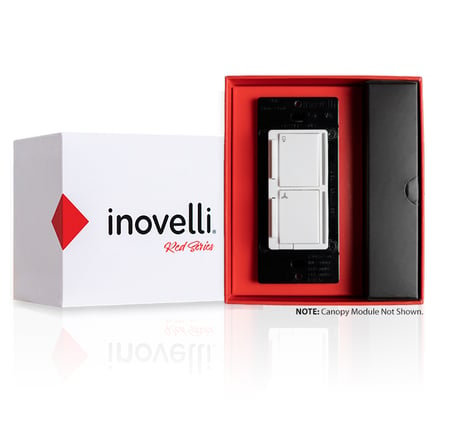
Product Image
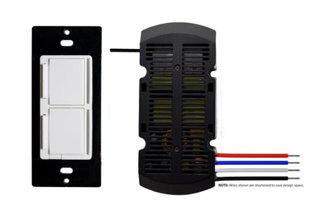
Switch and Module


1 - Dimming Speed - Light
This changes the speed in which the attached light dims up or down. A setting of 0 should turn the light immediately on or off (almost like an on/off switch). Increasing the value should slow down the transition speed.Size: 1 byte
Default: 3
Minimum: 0
Maximum: 100
Possible values
| From | To | Desription |
|---|---|---|
| 0 | 100 | Speed at which light dims up or down (increments) |
2 - Dimming Speed (From Switch) - Light
This changes the speed in which the attached light dims up or down when controlled from the physical switch. A setting of 0 should turn the light immediately on or off (almost like an on/off switch). Increasing the value should slow down the transition speed. A setting of 99 should keep this in sync with parameter 1.Size: 1 byte
Default: 99
Minimum: 0
Maximum: 99
Possible values
| From | To | Desription |
|---|---|---|
| 0 | 98 | Speed at which light dims up and down (from switch) |
| 99 | 99 | Sync to Parameter 1 |
3 - Ramp Rate
This changes the speed in which the attached light turns on or off. For example, when a user sends the switch a basicSet(value: 0xFF) or basicSet(value: 0x00), this is the speed in which those actions take place. A setting of 0 should turn the light immediately on or off (almost like an on/off switch). Increasing the value should slow down the transition speed. A setting of 99 should keep this in sync with parameter 1.Size: 1 byte
Default: 99
Minimum: 0
Maximum: 99
Possible values
| From | To | Desription |
|---|---|---|
| 1 | 98 | Speed at which the light turns on and off |
| 99 | 99 | Sync to Parameter 1 |
4 - Ramp Rate (From Switch)
This changes the speed in which the attached light turns on or off from the physical switch. For example, when a user presses the up or down button, this is the speed in which those actions take place. A setting of 0 should turn the light immediately on or off (almost like an on/off switch). Increasing the value should slow down the transition speed. A setting of 99 should keep this in sync with parameter 1.Size: 1 byte
Default: 99
Minimum: 0
Maximum: 99
Possible values
| From | To | Desription |
|---|---|---|
| 0 | 98 | Speed at which the light turns on and off (from switch) |
| 99 | 99 | Sync to Parameter 1 |
5 - Minimum Level – Light
The minimum level that the dimmer allows the bulb to be dimmed to. Useful when the user has a bulb that does not turn on at a lower level.Size: 1 byte
Default: 1
Minimum: 1
Maximum: 45
Possible values
| From | To | Desription |
|---|---|---|
| 1 | 45 | Minimum % level the bulb can be dimmed down to |
6 - Maximum Level – Light
The maximum level that the dimmer allows the bulb to be dimmed to. Useful when the user has an LED bulb that reaches its maximum level before the dimmer value of 99.Size: 1 byte
Default: 99
Minimum: 55
Maximum: 99
Possible values
| From | To | Desription |
|---|---|---|
| 55 | 99 | Maximum % level the bulb can be dimmed up to |
7 - Minimum Level – Fan
The minimum level that the dimmer allows the fan to be dimmed to. Useful when the user has a fan that does not turn on at a lower level.Size: 1 byte
Default: 1
Minimum: 1
Maximum: 45
Possible values
| From | To | Desription |
|---|---|---|
| 1 | 45 | Minimum % level the fan can be dimmed down to |
8 - Name: Maximum Level – Fan
The maximum level that the dimmer allows the fan to be dimmed to.Size: 1 byte
Default: 99
Minimum: 55
Maximum: 99
Possible values
| From | To | Desription |
|---|---|---|
| 55 | 99 | Maximum % level the fan can be dimmed up to |
9 - Invert Switch
Inverts the switch (Tap Down = On, Tap Up = Off). 0 = Disabled, 1 = EnabledSize: 1 byte
Default: 0
Minimum: 0
Maximum: 1
Possible values
| From | To | Desription |
|---|---|---|
| 0 | 0 | Disabled |
| 1 | 1 | Enabled |
10 - Auto Off Timer – Light
Automatically turns the light off after this many seconds. When the switch is turned on a timer is started that is the duration of this setting. When the timer expires, the switch is turned off.Size: 2 bytes
Default: 0
Minimum: 0
Maximum: 32767
Possible values
| From | To | Desription |
|---|---|---|
| 0 | 0 | Disabled |
| 1 | 32767 | Seconds |
11 - Auto Off Timer – Fan
Automatically turns the fan off after this many seconds. When the fan is turned on a timer is started that is the duration of this setting. When the timer expires, the fan is turned off.Size: 2 bytes
Default: 0
Minimum: 0
Maximum: 32767
Possible values
| From | To | Desription |
|---|---|---|
| 0 | 0 | Disabled |
| 1 | 32767 | Seconds |
12 - Default Level (Local) – Light
Default level for the dimmer when it is powered on from the local switch. A setting of 0 means that the switch will return to the level that it was on before it was turned off.Size: 1 byte
Default: 0
Minimum: 0
Maximum: 99
Possible values
| From | To | Desription |
|---|---|---|
| 0 | 0 | Sets back to light level prior to switch turning off |
| 1 | 99 | Sets light to a certain default dim level (ie: 1-99%) when powered on |
13 - Default Level (Z-Wave) – Light
Default level for the dimmer when it is powered on from a Z-Wave command. A setting of 0 means that the switch will return to the level that it was on before it was turned off.Size: 1 byte
Default: 0
Minimum: 0
Maximum: 99
Possible values
| From | To | Desription |
|---|---|---|
| 0 | 0 | Sets back to light level prior to switch turning off - via Z-Wave Command |
| 1 | 99 | Sets light to a certain default dim level (ie: 1-99%) when powered on - via Z-Wave Command |
14 - Default Level (Local) – Fan
Default level for the fan when it is powered on from the local switch. A setting of 0 means that the switch will return to the level that it was on before it was turned offSize: 1 byte
Default: 0
Minimum: 0
Maximum: 99
Possible values
| From | To | Desription |
|---|---|---|
| 0 | 0 | Sets back to fan level prior to switch turning off |
| 1 | 99 | Sets fan to a certain default dim level (ie: 1-99%) when powered on |
15 - Default Level (Z-Wave) – Fan
Default level for the fan when it is powered on from a Z-Wave command. A setting of 0 means that the switch will return to the level that it was on before it was turned off.Size: 1 byte
Default: 0
Minimum: 0
Maximum: 99
Possible values
| From | To | Desription |
|---|---|---|
| 0 | 0 | Sets back to fan level prior to switch turning off - Z-Wave |
| 1 | 99 | Sets fan to a certain default dim level (ie: 1-99%) when powered on - Z-Wave |
16 - State After Power Restored – Light
The state the switch should return to once power is restored after power failure. 0 = off, 1-99 = level, 100=previousSize: 1 byte
Default: 100
Minimum: 0
Maximum: 100
Possible values
| From | To | Desription |
|---|---|---|
| 0 | 0 | Off |
| 1 | 99 | Turns on to a certain percentage (1-99%) |
| 100 | 100 | Returns to previous state the light was in prior to a power outage |
17 - State After Power Restored – Fan
The state the switch should return to once power is restored after power failure. 0 = off, 1-99 = level, 100=previous.Size: 1 byte
Default: 0
Minimum: 0
Maximum: 100
Possible values
| From | To | Desription |
|---|---|---|
| 0 | 0 | Off |
| 1 | 99 | Turns on to a certain percentage (1-99%) |
| 100 | 100 | Returns to previous state the fan was in prior to power outage |
18 - Default LED Strip Color – Light
This is the color of the Light LED strip represented as part of the HUE color wheel. Since the wheel has 360 values and this parameter only has 255, the following equation can be used to determine the color: value/255 * 350 = Hue color wheel valueSize: 1 byte
Default: 170
Minimum: 0
Maximum: 255
Possible values
| From | To | Desription |
|---|---|---|
| 0 | 255 | Color values |
19 - Default LED Strip Intensity – Light
This is the intensity of the LED strip.Size: 1 byte
Default: 5
Minimum: 0
Maximum: 9
Possible values
| From | To | Desription |
|---|---|---|
| 0 | 9 | Intensity of the LED strip |
20 - Default LED Strip Color – Fan
This is the color of the Fan LED strip represented as part of the HUE color wheel. Since the wheel has 360 values and this parameter only has 255, the following equation can be used to determine the color: value/255 * 350 = Hue color wheel valueSize: 1 byte
Default: 170
Minimum: 0
Maximum: 255
Possible values
| From | To | Desription |
|---|---|---|
| 0 | 255 | Color values |
21 - Default LED Strip Intensity – Fan
This is the intensity of the fan LED strip.Size: 1 byte
Default: 5
Minimum: 0
Maximum: 9
Possible values
| From | To | Desription |
|---|---|---|
| 0 | 9 | Intensity of the Fan LED strip |
22 - Default LED Strip Intensity (When OFF) – Light
This is the intensity of the Light LED strip when the switch is off. This is useful for users to see the light switch location when the lights are off.Size: 1 byte
Default: 1
Minimum: 0
Maximum: 9
Possible values
| From | To | Desription |
|---|---|---|
| 0 | 9 | Intensity of the Light LED strip (when lights are off) |
23 - Default LED Strip Intensity (When OFF) – Fan
This is the intensity of the Fan LED strip when the switch is off. This is useful for users to see the light switch location when the lights are off.Size: 1 byte
Default: 1
Minimum: 0
Maximum: 9
Possible values
| From | To | Desription |
|---|---|---|
| 0 | 9 | Intensity of the Fan LED strip (when fan is off) |
24 - LED Strip Effect – Light
This will allow you to add some sweet effects to your LED Bar (i.e.: pulse, chase, solid, etc). Byte 1 = Color, Byte 2 = Brightness Level, Byte 3 = Effect, Byte 4 = Duration. *Please see website for further instructions on how to set this upSize: 4 bytes
Default: 0
Minimum: 0
Maximum: 4294967295
Possible values
| From | To | Desription |
|---|---|---|
| 0 | 4294967295 | Please see website instructions to set this up: https://nathanfiscus.github.io/inovelli-notification-calc/ |
25 - LED Strip Effect – Fan
This will allow you to add some sweet effects to your LED Bar (i.e.: pulse, chase, solid, etc). Byte 1 = Color, Byte 2 = Brightness Level, Byte 3 = Effect, Byte 4 = Duration. *Please see website for further instructions on how to set this upSize: 4 bytes
Default: 0
Minimum: 0
Maximum: 4294967295
Possible values
| From | To | Desription |
|---|---|---|
| 0 | 4294967295 | Please see website instructions to set this up: https://nathanfiscus.github.io/inovelli-notification-calc/ |
26 - Timeout for LED Bar – Light
When the LED strip is disabled (Light LED Strip Intensity is set to 0), this setting allows the LED strip to turn on temporarily while being adjusted.Size: 1 byte
Default: 3
Minimum: 0
Maximum: 10
Possible values
| From | To | Desription |
|---|---|---|
| 0 | 0 | Disabled |
| 1 | 10 | Intensity level |
27 - Name: Timeout for LED Bar – Fan
When the LED strip is disabled (Fan LED Strip Intensity is set to 0), this setting allows the LED strip to turn on temporarily while being adjusted.Size: 1 byte
Default: 3
Minimum: 0
Maximum: 10
Possible values
| From | To | Desription |
|---|---|---|
| 0 | 0 | Disabled |
| 1 | 10 | Intensity Level |
28 - Active Power Reports
The power level change that will result in a new power report being sent. The value is a percentage of the previous report. 0 = disabled.Size: 1 byte
Default: 10
Minimum: 0
Maximum: 100
Possible values
| From | To | Desription |
|---|---|---|
| 0 | 0 | Disabled |
| 1 | 100 | Percentage of the previous report |
29 - Periodic Power & Energy Reports
Time period between consecutive power & energy reports being sent (in seconds). The timer is reset after each report is sentSize: 2 bytes
Default: 3600
Minimum: 0
Maximum: 32767
Possible values
| From | To | Desription |
|---|---|---|
| 0 | 0 | Disabled |
| 1 | 32767 | Seconds |
30 - Energy Reports
Energy level change which will result in sending a new energy report. Available settings: 1-127 (0.01-1.27 kWh) 0 = disabled.Size: 1 byte
Default: 10
Minimum: 0
Maximum: 100
Possible values
| From | To | Desription |
|---|---|---|
| 0 | 0 | Disabled |
| 1 | 100 | Percentage of the previous report |
Put your hub/gateway into inclusion mode and hold down Button A (top of the config button -- normally used to dim up on the lights) and press Button B (light button) three (3) times. If you've successfully entered inclusion, the LED bars will pulse blue. Once included to the network, the LED bars will flash GREEN (they will flash RED if unsuccessful).
Put your hub/gateway into exclusion mode and hold down Button A (top of the config button -- normally used to dim up on the lights) and press Button B (light button) three (3) times. If you've successfully entered exclusion, the LED bars will pulse blue. Once excluded to the network, the LED bars will flash GREEN (they will flash RED if unsuccessful).
You may hold the Light Level Button (A) + Light On/Off Button (B) for 20 seconds or use a certified controller to remove the device from your network to factory default. Only use this procedure in the event that the network primary controller is missing or otherwise inoperable.
Configuration/Favorites Buttons: This switch allows for ultimate customization via the Configuration Buttons (rather than via a Z-Wave HUB) such as changing the dimming speed, fan speed, minimum/maximum dim level, invert switch, default dim level (local & Z-Wave), the power on state, LED Indicator Color, LED Indicator Intensity, and LED Indicator Intensity (When Off). In addition, the config button doubles as a favorites button allowing you to create your favorite scene (Z-Wave Central Scene) and press the config/favorite button to activate it. LED Bar Notifications: The LED Bar will alert you when an action has taken place (ie: Door is unlocked after 10pm, your switch will light up Red or your alarm panel is armed, it can flash green, etc). Central Scene Control: Allows up to 11 different scenes to be added to your switch (10x on the Paddles, 1x on the Config/Favorites Button). A use-case would be: Double Tap down on the switch to activate a bedtime scene that turns off all smart lights, locks the doors, and sets the temperature to 68. Smart Bulb Compatible: The internal relay can be disabled allowing for full control of Smart Bulbs (Z-Wave bulbs preferred for maximum control). This fixes the issue of when someone flips a switch and turns off power to your smart bulb (causing it to go offline). Now, you can disable the internal relay and send a scene command to turn on/off your bulb. Or directly associate the switch to the bulb to dim up/down and send a scene command to change the colors. OTA (Over-the-Air) Enabled: As with all our devices, the dimmer allows you to receive our latest firmware updates (NOTE: Please make sure your HUB supports this).
The QR Code can be found on the front of the switch.
Please see Page 9 of our Manual. It will literally be like writing a thesis statement.
N/A
| Type | Value(s) |
|---|
| Meter type |
|---|
| Electric Meter Consumption |