Aeotec
Door / Window Sensor 7 Pro
ZWA012-A
Notification Sensor
HW: 1 FW: 1.00
ZGM130
7.12.2
0x0371 (881)
0x0102 (258)
0x000C (12)
ZC12-20080085
2020-08-06 15:08:36.074166
N/A
Enhanced 232 Slave
Reporting Sleeping Slave
Yes
A 700 series sensor, which monitors if your window is open, closed or tilted. Can be connected to other sensors via a binary dry input.
Aeotec Door/ Window Sensor 7 Pro is built on the 700 series Z-Wave technology. Its a small window position sensor for your smart home, it monitors window and their exact opening position and lets your know when a window is tilted or completely opened. It also supports connecting external binary sensors with a dry contact through the dry binary contact of the Door/ Window sensor. Using the latest technology it supports the highest Z-Wave security level of S2 and SmartStart.
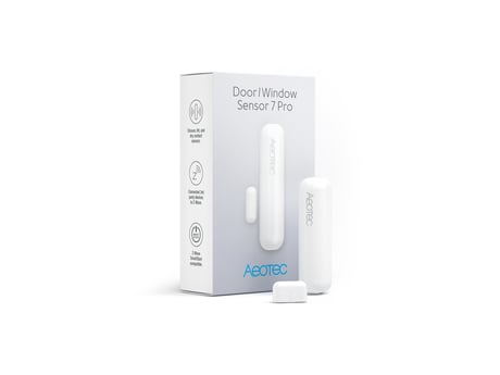
Product Image


1 - Sensor Operation Mode
This parameter defines if the internal magnet sensor or the external terminal input is detected and used to issue alarm notification. There is always one input active only. The other sensor input the deactivated.Size: 1 byte
Default: 0
Minimum: 0
Maximum: 1
Possible values
| From | To | Desription |
|---|---|---|
| 0 | 0 | Internal Magnet Sensor Used and scene activation enabled |
| 1 | 0 | External Terminal Inputs Used and scene activation disabled |
2 - Dry Contact Operation Mode
Parameter defines how dry contact will operate with the sensor or switch that is connected to the dry contact terminals. 0 - NO Toggle / Follow state will follow the input of the dry contact terminals where OFF is CLOSED, and ON is OPEN. 1 - NC Toggle / Follow state will follow the input of the dry contact terminals where ON is CLOSED, and OFF is OPEN. 2 - NO save state will allow state of sensor to toggle OPEN/CLOSE based on OFF to ON signal. 3 - NC save state will allow state of sensor to toggle OPEN/CLOSE based on ON toOFF signal.Size: 1 byte
Default: 0
Minimum: 0
Maximum: 3
Possible values
| From | To | Desription |
|---|---|---|
| 0 | 0 | NO Toggle / Follow state will follow the input of the dry contact terminals where OFF is CLOSED, and ON is OPEN. |
| 1 | 1 | NC Toggle / Follow state will follow the input of the dry contact terminals where ON is CLOSED, and OFF is OPEN. |
| 2 | 2 | NO save state will allow state of sensor to toggle OPEN/CLOSE based on OFF to ON signal. |
| 3 | 3 | NC save state will allow state of sensor to toggle OPEN/CLOSE based on ON toOFF signal. |
3 - Sensor State Polarity
This parameter defines the polarity of the magnet sensor.Size: 1 byte
Default: 0
Minimum: 0
Maximum: 1
Possible values
| From | To | Desription |
|---|---|---|
| 0 | 0 | Closed when Magnet near |
| 1 | 0 | Opened when Magnet near |
4 - Visual LED Indications
This parameter defines when the red LED will indicate events. Disabling all indications may extend battery life.Size: 1 byte
Default: 7
Minimum: 0
Maximum: 7
Possible values
| From | To | Desription |
|---|---|---|
| 0 | 0 | LED indication Off |
| 1 | 0 | Open/Close Status Change |
| 2 | 0 | Wake Up |
| 3 | 0 | Open/Close Status Change + Wake Up (1+2 summarized) |
| 4 | 0 | Device Tampering |
| 5 | 0 | Open/Close Status Change + Device Tampering (1 + 5 summarized) |
| 6 | 0 | Wake Up + Device Tampering (2 + 4 summarized) |
| 7 | 0 | All LED indications on (values 1 + 2 + 4 summarized) |
5 - Range Test after double click
Allows to enable the activation of a Z-Wave range test with double clicking the tamper switch.Size: 1 byte
Default: 0
Minimum: 0
Maximum: 1
Possible values
| From | To | Desription |
|---|---|---|
| 0 | 0 | Disabled |
| 1 | 0 | Enabled |
6 - 2nd Association Group Trigger
This parameter defines the status of the magnet switch that causes sending a BASIC command to all devices of Association Group 2.Size: 1 byte
Default: 0
Minimum: 0
Maximum: 2
Possible values
| From | To | Desription |
|---|---|---|
| 0 | 0 | Switch after Open and Close |
| 1 | 0 | Switch after Open |
| 2 | 0 | Switch after Close |
7 - Command Sent to Devices of Association Group 2
This parameter defines which commands is sent to 2nd Association GroupSize: 1 byte
Default: 2
Minimum: 0
Maximum: 2
Possible values
| From | To | Desription |
|---|---|---|
| 0 | 0 | On |
| 1 | 0 | Off |
| 2 | 0 | On and Off |
8 - BASIC command "On event" value
This is the BASIC command value sent in case of "On" event.Size: 1 byte
Default: 255
Minimum: 0
Maximum: 255
Possible values
| From | To | Desription |
|---|---|---|
| 0 | 99 | Value |
| 255 | 255 | Value |
9 - BASIC command "Off event" value
This is the BASIC command value sent in case of "Off" event.Size: 1 byte
Default: 0
Minimum: 0
Maximum: 255
Possible values
| From | To | Desription |
|---|---|---|
| 0 | 99 | Value |
| 255 | 255 | Value |
10 - Time Delay of "On" command frame
On command is sent after a delay defined in this parameter.Size: 2 bytes
Default: 0
Minimum: 0
Maximum: 32400
Possible values
| From | To | Desription |
|---|---|---|
| 0 | 32400 | seconds |
11 - Time Delay of "Off" command frame
Off command is sent after a delay defined in this parameter.Size: 2 bytes
Default: 0
Minimum: 0
Maximum: 32400
Possible values
| From | To | Desription |
|---|---|---|
| 0 | 32400 | seconds |
12 - Delay of Tamper Alarm Cancellation
Time a tamper alarm is delayed.Size: 2 bytes
Default: 0
Minimum: 0
Maximum: 32400
Possible values
| From | To | Desription |
|---|---|---|
| 0 | 32400 | seconds |
13 - Reporting Tamper Alarm Cancellation
This parameter defines if the alarm cancellation event is reported.Size: 1 byte
Default: 1
Minimum: 0
Maximum: 1
Possible values
| From | To | Desription |
|---|---|---|
| 0 | 0 | Do not send Report |
| 1 | 0 | Send Report |
14 - Central Scene Event Functionality
This parameter enables/disables the central scene function.Size: 1 byte
Default: 0
Minimum: 0
Maximum: 1
Possible values
| From | To | Desription |
|---|---|---|
| 0 | 0 | Disabled |
| 1 | 0 | Enabled |
15 - Tilt Sensor Functionality
This parameter enables/disables the tilt function.Size: 1 byte
Default: 1
Minimum: 0
Maximum: 1
Possible values
| From | To | Desription |
|---|---|---|
| 0 | 0 | Disabled |
| 1 | 0 | Enabled |
16 - Tilt Sensor State
This parameter allows to set in what state is door/window when the tilt is in an OFF state.Size: 1 byte
Default: 0
Minimum: 0
Maximum: 1
Possible values
| From | To | Desription |
|---|---|---|
| 0 | 0 | OFF when sensor is vertical |
| 1 | 0 | ON when sensor is vertical |
17 - 5th Association Group triggers
Parameter defines events which result in sending On/Off commands to devices added to the 2nd Association Group. These commands are sent alternately to switch the devices On and Off. Commands represent the values of BASIC SET command frames.Size: 1 byte
Default: 0
Minimum: 0
Maximum: 2
Possible values
| From | To | Desription |
|---|---|---|
| 0 | 0 | Switch after Open and Close |
| 1 | 1 | Switch after Open |
| 2 | 2 | Switch after Close |
18 - Commands sent to 5th Association Group
Command frames sent to devices added to the 5th association group.Size: 1 byte
Default: 2
Minimum: 0
Maximum: 2
Possible values
| From | To | Desription |
|---|---|---|
| 0 | 0 | On |
| 1 | 1 | Off |
| 2 | 2 | On and Off |
19 - Value of ON command frame sent to 5th Associatio
The value of 0 turns OFF the device, 255 turns it On. In case of associating the Dimmer or Roller Shutter module, values 1-99 allow to set an Associated device to a specified level. 0-99 or 255Size: 1 byte
Default: 255
Minimum: 0
Maximum: 255
Possible values
| From | To | Desription |
|---|---|---|
| 0 | 99 | Value |
| 255 | 255 | Value |
21 - Tilt sensitivity
You can use this parameter to adjust the tilt sensitivity if the tilt is too low or too high.Size: 1 byte
Default: 50
Minimum: 1
Maximum: 100
Possible values
| From | To | Desription |
|---|---|---|
| 1 | 100 | Tilt Sensitivity |
255 - Reset Parameter
0 – Nothing happens 0x55555555 – Completely factory reset sensor and send device reset locally notification. All other values – Reset all Parameter settings to their default settings.Size: 4 bytes
Default: 0
Minimum: 0
Maximum: 1431655765
Possible values
| From | To | Desription |
|---|---|---|
| 1 | 1431655764 | Reset all Parameter settings to their default settings. |
| 1431655765 | 1431655765 | Completely factory reset sensor and send device reset locally notification. |
Inclusion 1. Open the housing. 2. Remove the battery protection. 3. Press the tamper on the side of the appliance three times quickly.
Exclusion 1. Open the housing. 2. Press the tamper on the side of the appliance three times quickly.
The Node Information Frame (NIF) is the business card of a Z-Wave device. It contains information about the device type and the technical capabilities. The inclusion and exclusion of the device is confirmed by sending out a Node Information Frame. Beside this it may be needed for certain network operations to send out a Node Information Frame. To issue a NIF execute the following action: Press the tamper once
Reset to factory default This device also allows to be reset without any involvement of a Z-Wave controller. This procedure should only be used when the primary controller is inoperable. Once Cover is removed and the tamper switch is tripped, push the tamper for 5 seconds until the RED LED blinks once. Then release tamper and push it again for 5 seconds while the RED LED is blinking until the GREEN LED blinks once.
- Connection to binary dry contact sensors - Scene control with a button or button switch, which is connected to the input terminals of the sensor
The DSK for the S2 DSK can be found inside the sensors packaging.
| Type | Value(s) |
|---|
| Group | Type |
|---|---|
| Access Control |
|
| Home Security | Cover status: Tampering, product cover removed |