FIBARO
FGS-224
FGS-224
On/Off Power Switch
HW: 4 FW: 5.00
ZM5101
6.82.00
0x010F (271)
0x0204 (516)
0x1000 (4096)
ZC10-20096968
2020-09-03 10:12:59.399038
N/A
Enhanced 232 Slave
Always On Slave
The remotely operated FIBARO Double Smart Module is designed to turn electrical devices or circuits on and off.
The remotely operated FIBARO Double Smart Module is designed to turn electrical devices or circuits on and off. Double Smart Module allows to control two devices or circuits. The compact size of the device allows for the product to be installed in the housings of other devices. The devices can be controlled either via the Z-Wave™ network or with buttons connected directly to them.
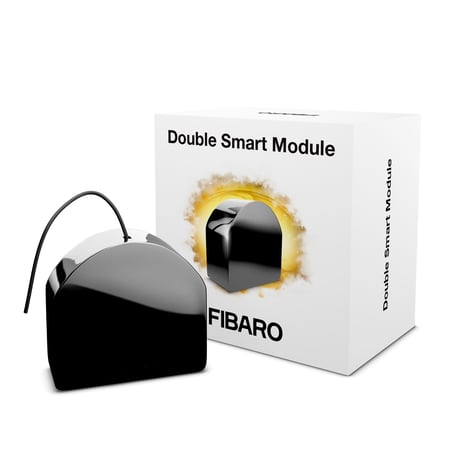
Product Image


1 - Remember relays state
This parameter determines the state of relays after power supply failure (e.g. power outage). For auto OFF and flashing modes the parameter is not relevant and the relay will always remain switched off.Size: 1 byte
Default: 1
Minimum: 0
Maximum: 2
Possible values
| From | To | Desription |
|---|---|---|
| 0 | 0 | relays remain switched off after restoring power |
| 1 | 1 | restore remembered state of relays after restoring power |
| 2 | 2 | restore remembered state of relays after restoring power, but for toggle switches (parameter 20/21 set to 1) set the same state as the current state of the switches |
20 - S1 input – switch type
This parameter defines as what type the device should treat the switch connected to the S1 terminal.Size: 1 byte
Default: 0
Minimum: 0
Maximum: 2
Possible values
| From | To | Desription |
|---|---|---|
| 0 | 0 | momentary switch |
| 1 | 1 | toggle switch synchronized (contact closed - ON, contact opened - OFF) |
| 2 | 2 | toggle switch with memory (device changes status when switch changes status) |
21 - Parameter 2
This parameter defines as what type the device should treat the switch connected to the S2 terminal.Size: 1 byte
Default: 0
Minimum: 0
Maximum: 2
Possible values
| From | To | Desription |
|---|---|---|
| 0 | 0 | momentary switch |
| 1 | 1 | toggle switch synchronized (contact closed - ON, contact opened - OFF) |
| 2 | 2 | toggle switch with memory (device changes status when switch changes status) |
24 - Inputs orientation
This parameter allows reversing operation of S1 and S2 inputs without changing the wiring. Use in case of incorrect wiring.Size: 1 byte
Default: 0
Minimum: 0
Maximum: 1
Possible values
| From | To | Desription |
|---|---|---|
| 0 | 0 | default (S1 - 1st channel, S2 - 2nd channel) |
| 1 | 1 | reversed (S1 - 2nd channel, S2 - 1st channel) |
25 - Outputs orientation
This parameter allows reversing operation of Q1 and Q2 outputs without changing the wiring. Use in case of incorrect wiring.Size: 1 byte
Default: 0
Minimum: 0
Maximum: 1
Possible values
| From | To | Desription |
|---|---|---|
| 0 | 0 | default (Q1 - 1st channel, Q2 - 2nd channel) |
| 1 | 1 | reversed (Q1 - 2nd channel, Q2 - 1st channel) |
30 - Alarm configuration - 1st slot
This parameter determines to which alarm frames and how the device should react. The parameters consist of 4 bytes, three most significant bytes are set according to the official Z-Wave protocol specification.Default value [0x00, 0x00, 0x00, 0x00] (disabled). The 4 bytes must be converted to a single decimal value to be entered in the gateway sending the configuration parameter value. Example: Event: Home Security (0x07) Status: Motion Detected (0x08) Parameter: None (0x00) Action: turn ON (0x01)=0x07080001 which is 117964801 decimal to be entered in the gateway.Size: 4 bytes
Default: 0
Minimum: 0
Maximum: 2147483647
Possible values
| From | To | Desription |
|---|---|---|
| 0 | 255 | [LSB] – action |
| 256 | 65535 | Event/State Parameters |
| 65536 | 16777215 | Notification Status |
| 16777216 | 2147483647 | [MSB] – Notification Type |
31 - Alarm configuration - 2nd slot
This parameter determines to which alarm frames and how the device should react. The parameters consist of 4 bytes, three most significant bytes are set according to the official Z-Wave protocol specification. Default value [0x05, 0xFF, 0x00, 0x00] (Water alarm, any notification, no action). The 4 bytes must be converted to a single decimal value to be entered in the gateway sending the configuration parameter value. Example: Event: Home Security (0x07) Status: Motion Detected (0x08) Parameter: None (0x00) Action: turn ON (0x01)=0x07080001 which is 117964801 decimal to be entered in the gateway.Size: 4 bytes
Default: 100597769
Minimum: 0
Maximum: 2147483647
Possible values
| From | To | Desription |
|---|---|---|
| 0 | 255 | [LSB] – action |
| 256 | 65535 | Event/State Parameters |
| 65536 | 16777215 | Notification Status |
| 16777216 | 2147483647 | [MSB] – Notification Type |
32 - Alarm configuration - 3rd slot
This parameter determines to which alarm frames and how the device should react. The parameters consist of 4 bytes, three most significant bytes are set according to the official Z-Wave protocol specification. Default value [0x01, 0xFF, 0x00, 0x00] (Smoke alarm, any notification, no action). The 4 bytes must be converted to a single decimal value to be entered in the gateway sending the configuration parameter value. Example: Event: Home Security (0x07) Status: Motion Detected (0x08) Parameter: None (0x00) Action: turn ON (0x01)=0x07080001 which is 117964801 decimal to be entered in the gateway.Size: 4 bytes
Default: 33488896
Minimum: 0
Maximum: 2147483647
Possible values
| From | To | Desription |
|---|---|---|
| 0 | 255 | [LSB] – action |
| 256 | 65535 | Event/State Parameters |
| 65536 | 16777215 | Notification Status |
| 16777216 | 2147483647 | [MSB] – Notification Type |
33 - Alarm configuration - 4th slot
This parameter determines to which alarm frames and how the device should react. The parameters consist of 4 bytes, three most significant bytes are set according to the official Z-Wave protocol specification. Default value [0x02, 0xFF, 0x00, 0x00] (CO alarm, any notification, no action). The 4 bytes must be converted to a single decimal value to be entered in the gateway sending the configuration parameter value. Example: Event: Home Security (0x07) Status: Motion Detected (0x08) Parameter: None (0x00) Action: turn ON (0x01)=0x07080001 which is 117964801 decimal to be entered in the gateway.Size: 4 bytes
Default: 50266112
Minimum: 0
Maximum: 2147483647
Possible values
| From | To | Desription |
|---|---|---|
| 0 | 255 | [LSB] – action |
| 256 | 65535 | Event/State Parameters |
| 65536 | 16777215 | Notification Status |
| 16777216 | 2147483647 | [MSB] – Notification Type |
34 - Alarm configuration - 5th slot
This parameter determines to which alarm frames and how the device should react. The parameters consist of 4 bytes, three most significant bytes are set according to the official Z-Wave protocol specification. Default value [0x041, 0xFF, 0x00, 0x00] (Heat alarm, any notification, no action). The 4 bytes must be converted to a single decimal value to be entered in the gateway sending the configuration parameter value. Example: Event: Home Security (0x07) Status: Motion Detected (0x08) Parameter: None (0x00) Action: turn ON (0x01)=0x07080001 which is 117964801 decimal to be entered in the gateway.Size: 4 bytes
Default: 83820544
Minimum: 0
Maximum: 2147483647
Possible values
| From | To | Desription |
|---|---|---|
| 0 | 255 | [LSB] – action |
| 256 | 65535 | Event/State Parameters |
| 65536 | 16777215 | Notification Status |
| 16777216 | 2147483647 | [MSB] – Notification Type |
35 - Alarm configuration – duration
This parameter defines duration of alarm sequence. When time set in this parameter elapses, alarm is cancelled and relays restore normal operation, but do not recover state from before the alarm.Size: 2 bytes
Default: 600
Minimum: 0
Maximum: 32400
Possible values
| From | To | Desription |
|---|---|---|
| 0 | 0 | infinite |
| 1 | 32400 | (1s-9h, 1s step) – duration |
40 - S1 input – scenes sent
This parameter determines which actions result in sending scene IDs assigned to them. Values can be combined (e.g. 1+2=3 means that scenes for single and double click are sent). Enabling scenes for triple click disables entering the device in learning mode by triple clicking.Size: 1 byte
Default: 15
Minimum: 0
Maximum: 15
Possible values
| From | To | Desription |
|---|---|---|
| 0 | 0 | no scenes sent |
| 1 | 1 | Key pressed 1 time |
| 2 | 2 | Key pressed 2 times |
| 4 | 4 | Key pressed 3 times |
| 8 | 8 | Key hold down and key released |
| 15 | 15 | All active |
41 - S2 input – scenes sent
This parameter determines which actions result in sending scene IDs assigned to them. Values can be combined (e.g. 1+2=3 means that scenes for single and double click are sent). Enabling scenes for triple click disables entering the device in learning mode by triple clicking.Size: 1 byte
Default: 15
Minimum: 0
Maximum: 15
Possible values
| From | To | Desription |
|---|---|---|
| 0 | 0 | no scenes sent |
| 1 | 1 | Key pressed 1 time |
| 2 | 2 | Key pressed 2 times |
| 4 | 4 | Key pressed 3 times |
| 8 | 8 | Key hold down and key released |
| 15 | 15 | All active |
150 - First channel – operating mode
This parameter allows to choose operating mode for channel controlled with Q/Q1 output. For timed modes (value 1, 2 or 3), time is set with parameter 154 and reaction to input change is set with parameter 152.Size: 1 byte
Default: 0
Minimum: 0
Maximum: 3
Possible values
| From | To | Desription |
|---|---|---|
| 0 | 0 | standard operation |
| 1 | 1 | delayed OFF |
| 2 | 2 | auto OFF |
| 3 | 3 | flashing |
152 - First channel - reaction to input change in delayed/auto OFF modes
This parameter determines how the device reacts when changing state of S1 input in timed modes for first channel.Size: 1 byte
Default: 0
Minimum: 0
Maximum: 2
Possible values
| From | To | Desription |
|---|---|---|
| 0 | 0 | cancel mode and set default state |
| 1 | 1 | no reaction, mode runs until it ends |
| 2 | 2 | reset timer, start counting time from the beginning |
153 - Second channel – reaction to input change in delayed/ auto OFF modes
This parameter determines how the device reacts when changing state of S2 input in timed modes for second channel.Size: 1 byte
Default: 0
Minimum: 0
Maximum: 2
Possible values
| From | To | Desription |
|---|---|---|
| 0 | 0 | cancel mode and set default state |
| 1 | 1 | no reaction, mode runs until it ends |
| 2 | 2 | reset timer, start counting time from the beginning |
154 - First channel – time parameter for delayed/auto OFF and flashing modes
This parameter allows to set time parameter used in timed modes for first channel. For delayed/ auto OFF modes it determines duration, for flashing mode it determines cycle period.Size: 2 bytes
Default: 5
Minimum: 0
Maximum: 32000
Possible values
| From | To | Desription |
|---|---|---|
| 0 | 0 | 0.1 seconds |
| 1 | 32000 | 0.1-3200 seconds, 0.1s step |
155 - Second channel – time parameter for delayed/auto OFF and flashing modes
This parameter allows to set time parameter used in timed modes for second channel. For delayed/auto OFF modes it determines duration, for flashing mode it determines cycle period.Size: 2 bytes
Default: 5
Minimum: 0
Maximum: 32000
Possible values
| From | To | Desription |
|---|---|---|
| 0 | 0 | 0.1 seconds |
| 1 | 32000 | 0.1-3200 seconds, 0.1s step |
156 - ParaS1 input – Switch ON value sent to 2nd association group
This parameter defines value sent with Switch ON command to devices in 2nd association group when using S1 input.Size: 2 bytes
Default: 255
Minimum: 0
Maximum: 255
Possible values
| From | To | Desription |
|---|---|---|
| 0 | 0 | turn off |
| 1 | 99 | turn on and set level |
| 255 | 255 | turn on with last level |
157 - S1 input – Switch OFF value sent to 2nd association group
This parameter defines value sent with Switch OFF command to devices in 2nd association group when using S1 input.Size: 2 bytes
Default: 0
Minimum: 0
Maximum: 255
Possible values
| From | To | Desription |
|---|---|---|
| 0 | 0 | turn off |
| 1 | 99 | turn on and set level |
| 255 | 255 | turn on with last level |
158 - S1 input – Double Click value sent to 2nd association group
This parameter defines value sent with Double Click command to devices in 2nd association group when using S1 input.Size: 2 bytes
Default: 99
Minimum: 0
Maximum: 255
Possible values
| From | To | Desription |
|---|---|---|
| 0 | 0 | turn off |
| 1 | 99 | turn on and set level |
| 255 | 255 | turn on with last level |
159 - S2 input – Switch ON value sent to 3rd association group
This parameter defines value sent with Switch ON command to devices in 3rd association group when using S2 input.Size: 2 bytes
Default: 255
Minimum: 0
Maximum: 255
Possible values
| From | To | Desription |
|---|---|---|
| 0 | 0 | turn off |
| 1 | 99 | turn on and set level |
| 255 | 255 | turn on with last level |
160 - S2 input – Switch OFF value sent to 3rd association group
This parameter defines value sent with Switch OFF command to devices in 3rd association group when using S2 input.Size: 2 bytes
Default: 0
Minimum: 0
Maximum: 255
Possible values
| From | To | Desription |
|---|---|---|
| 0 | 0 | turn off |
| 1 | 99 | turn on and set level |
| 255 | 255 | turn on with last level |
161 - S2 input – Double Click value sent to 3rd association group
This parameter defines value sent with Double Click command to devices in 3rd association group when using S2 input.Size: 2 bytes
Default: 99
Minimum: 0
Maximum: 255
Possible values
| From | To | Desription |
|---|---|---|
| 0 | 0 | turn off |
| 1 | 99 | turn on and set level |
| 255 | 255 | turn on with last level |
162 - Q/Q1 output type
This parameter determines type of Q/Q1 output.Size: 1 byte
Default: 0
Minimum: 0
Maximum: 1
Possible values
| From | To | Desription |
|---|---|---|
| 0 | 0 | Normally Open (relay contacts opened turned off, closed when turned on) |
| 1 | 1 | Normally Closed (relay contacts closed turned off, opened when turned on) |
163 - Q2 output type
This parameter determines type of Q2 output.Size: 1 byte
Default: 0
Minimum: 0
Maximum: 1
Possible values
| From | To | Desription |
|---|---|---|
| 0 | 0 | Normally Open (relay contacts opened turned off, closed when turned on) |
| 1 | 1 | Normally Closed (relay contacts closed turned off, opened when turned on) |
164 - Lock simultaneous switching of Q1 and Q2 outputs
When the lock is enabled, both outputs cannot be turned on at the same time.Size: 1 byte
Default: 0
Minimum: 0
Maximum: 1
Possible values
| From | To | Desription |
|---|---|---|
| 0 | 0 | lock disabled |
| 1 | 1 | lock enabled |
To add the device to the Z-Wave network manually: 1. Power the device. 2. Set the main controller in (Security/non-Security Mode) add mode (see the controller’s manual). 3. Quickly, three times click button connected to S1/S2 or the maintenance button. 4. LED will start blinking yellow, wait for the adding process to end. 5. If you are adding in Security S2 Authenticated, input the underlined part of the DSK (label on the bottom of the box). 6. Adding result will be confirmed by the Z-Wave controller’s message and the LED: • Green – successful (non-secure, S0, S2 non-authenticated), • Magenta – successful (Security S2 Authenticated), • Red – not successful.
To remove the device from the Z-Wave network: 1. Power the device. 2. Set the main controller into remove mode (see the controller’s manual). 3. Quickly, three times click the maintenance button. 4. LED will start blinking yellow, wait for the removing process to end. 5. Successful removing will be confirmed by the Z-Wave controller’s message and red LED colour.
1. Press and hold the maintenance button to enter the menu. 2. Release button when the device glows yellow. 3. Quickly click the button to confirm. 4. After few seconds the device will be restarted, which is signalled with red LED colour.
If you are adding in Security S2 Authenticated, input the underlined part of the DSK (label on the bottom of the box).
| Type | Value(s) |
|---|
| Group | Type |
|---|---|
| System | Heartbeat |