myTEM SmartHome
Radio I/O Modul
MTIOM-100-WL
Binary Switch
HW: 0 FW: 1.00:00.07
ZGM130
7.13.2
0x034E (846)
0x0001 (1)
0x000A (10)
ZC12-21020178
2021-02-02 20:25:06.80291
N/A
Enhanced 232 Slave
Always On Slave
The Radio IO Modul MTIOM-100-WL is a universal, Z-Wave compatible module from myTEM for extending your smart home system with additional inputs and outputs.
The Radio IO Modul MTIOM-100-WL is a universal, Z-Wave compatible module from myTEM for extending your smart home system with additional inputs and outputs. It is a Z-Wave device of the type Binary Switch for the use in Europe / Switzerland. Main use is for: - Switching of lights - Switching of single-phase fan motors - Switching of electric blinds or similar shading devices - Operation by means of buttons, sensors via the central server Functions: - Supply voltage 24 VDC ± 10% - Communication via Z-Wave mesh network - 6 digital inputs 24 VDC (DI1 – DI6) for e.g. external switches - 24 VDC power supply, 100 mA, for the digital inputs DI1 – DI6 (VDIout) - 4 analog inputs (AI1 – AI4), which can be used for 0-10 VDC or NTC-, PTC- or PT1000 sensors. Analog inputs can also be used as digital inputs 24 VDC. - 6 digital outputs with potential-free, relay 8 A, 250 VAC - Manual positions of the outputs via DIP switch for easy commissioning - The device is installed in a control cabinet, mounted on a 35 mm DIN rail
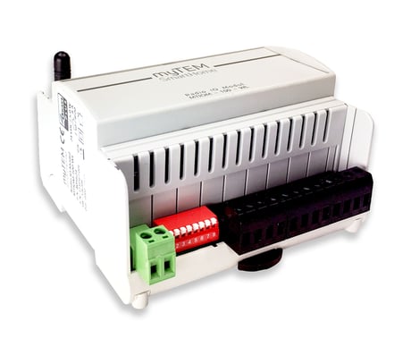
Product Image


1 - Heartbeat rate [min]
see manualSize: 2 bytes
Default: 60
Minimum: 1
Maximum: 1440
Possible values
| From | To | Desription |
|---|---|---|
| 1 | 1440 | Value tells at what interval [min] Heartbeat will be sent |
2 - DI 1 send enable
see manualSize: 2 bytes
Default: 0
Minimum: 0
Maximum: 2
Possible values
| From | To | Desription |
|---|---|---|
| 0 | 0 | Notifications for DI 1 are disabled |
| 1 | 1 | Binary Sensor Report for DI 1 is enabled |
| 2 | 2 | Central Scene Report for DI 1 is enabled |
3 - DI 1 send interval [min]
see manualSize: 2 bytes
Default: 50
Minimum: 1
Maximum: 1200
Possible values
| From | To | Desription |
|---|---|---|
| 1 | 1200 | Value tells at what interval [0.1min] notification for DI 1 will we sent |
4 - DI 2 send enable
see manualSize: 2 bytes
Default: 0
Minimum: 0
Maximum: 2
Possible values
| From | To | Desription |
|---|---|---|
| 0 | 0 | Notifications for DI 2 are disabled |
| 1 | 1 | Binary Sensor Report for DI 2 is enabled |
| 2 | 2 | Central Scene Report for DI 2 is enabled |
5 - DI 2 send interval [min]
see manualSize: 2 bytes
Default: 50
Minimum: 1
Maximum: 1200
Possible values
| From | To | Desription |
|---|---|---|
| 1 | 1200 | Value tells at what interval [0.1min] notification for DI 2 will we sent |
6 - DI 3 send enable
see manualSize: 2 bytes
Default: 0
Minimum: 0
Maximum: 2
Possible values
| From | To | Desription |
|---|---|---|
| 0 | 0 | Notifications for DI 3 are disabled |
| 1 | 1 | Binary Sensor Report for DI 3 is enabled |
| 2 | 2 | Central Scene Report for DI 3 is enabled |
7 - DI 3 send interval[min]
see manualSize: 2 bytes
Default: 50
Minimum: 1
Maximum: 1200
Possible values
| From | To | Desription |
|---|---|---|
| 1 | 1200 | Value tells at what interval [0.1min] notification for DI 3 will we sent |
8 - DI 4 send enable
see manualSize: 2 bytes
Default: 0
Minimum: 0
Maximum: 2
Possible values
| From | To | Desription |
|---|---|---|
| 0 | 0 | Notifications for DI 4 are disabled |
| 1 | 1 | Binary Sensor Report for DI 4 is enabled |
| 2 | 2 | Central Scene Report for DI 4 is enabled |
9 - DI 4 send interval [min]
see manualSize: 2 bytes
Default: 50
Minimum: 1
Maximum: 1200
Possible values
| From | To | Desription |
|---|---|---|
| 1 | 1200 | Value tells at what interval [0.1min] notification for DI 4 will we sent |
10 - DI 5 send enable
see manualSize: 2 bytes
Default: 0
Minimum: 0
Maximum: 2
Possible values
| From | To | Desription |
|---|---|---|
| 0 | 0 | Notifications for DI 5 are disabled |
| 1 | 1 | Binary Sensor Report for DI 5 is enabled |
| 2 | 2 | Central Scene Report for DI 5 is enabled |
11 - DI 5 send interval [min]
see manualSize: 2 bytes
Default: 50
Minimum: 1
Maximum: 1200
Possible values
| From | To | Desription |
|---|---|---|
| 1 | 1200 | Value tells at what interval [0.1min] notification for DI 5 will we sent |
12 - DI 6 send enable
see manualSize: 2 bytes
Default: 0
Minimum: 0
Maximum: 2
Possible values
| From | To | Desription |
|---|---|---|
| 0 | 0 | Notifications for DI 6 are disabled |
| 1 | 1 | Binary Sensor Report for DI 6 is enabled |
| 2 | 2 | Central Scene Report for DI 6 is enabled |
13 - DI 6 send interval [min]
see manualSize: 2 bytes
Default: 50
Minimum: 1
Maximum: 1200
Possible values
| From | To | Desription |
|---|---|---|
| 1 | 1200 | Value tells at what interval [0.1min] notification for DI 6 will we sent |
14 - AI 1 send enable
see manualSize: 2 bytes
Default: 0
Minimum: 0
Maximum: 1
Possible values
| From | To | Desription |
|---|---|---|
| 0 | 0 | Sending AI 1 values disabled |
| 1 | 1 | Sending AI 1 values enabled |
15 - AI 1 sensor select
see manualSize: 2 bytes
Default: 0
Minimum: 0
Maximum: 5
Possible values
| From | To | Desription |
|---|---|---|
| 0 | 0 | Configure AI 1 for NTC 5k Ohm thermistor |
| 1 | 1 | Configure AI 1 for NTC 10k Ohm thermistor |
| 2 | 2 | Configure AI 1 for PTC 1k Ohm thermistor |
| 3 | 3 | Configure AI 1 for PT1000 thermistor |
| 4 | 4 | Configure AI 1 for 0 - 10V sensor |
| 5 | 5 | Configure AI 1 for digital input |
16 - AI 1 send interval [min]
see manualSize: 2 bytes
Default: 50
Minimum: 1
Maximum: 1200
Possible values
| From | To | Desription |
|---|---|---|
| 1 | 1200 | Value tells at what interval [0.1min] sensor values for AI 1 will be sent |
17 - AI 1 send delta temp [K]
see manualSize: 2 bytes
Default: 5
Minimum: 1
Maximum: 100
Possible values
| From | To | Desription |
|---|---|---|
| 1 | 100 | Value tells at what temperature difference [0.1K]for AI 1 will be sent |
18 - AI 1 send delta volt [V]
see manualSize: 2 bytes
Default: 5
Minimum: 1
Maximum: 100
Possible values
| From | To | Desription |
|---|---|---|
| 1 | 100 | Value tells at what voltage difference [0.1V]for AI 1 will be sent |
19 - AI 2 send enable
see manualSize: 2 bytes
Default: 0
Minimum: 0
Maximum: 1
Possible values
| From | To | Desription |
|---|---|---|
| 0 | 0 | Sending AI 2 values disabled |
| 1 | 1 | Sending AI 2 values enabled |
20 - AI 2 sensor select
see manualSize: 2 bytes
Default: 0
Minimum: 0
Maximum: 5
Possible values
| From | To | Desription |
|---|---|---|
| 0 | 0 | Configure AI 2 for NTC 5k Ohm thermistor |
| 1 | 1 | Configure AI 2 for NTC 10k Ohm thermistor |
| 2 | 2 | Configure AI 2 for PTC 1k Ohm thermistor |
| 3 | 3 | Configure AI 2 for PT1000 thermistor |
| 4 | 4 | Configure AI 2 for 0 - 10V sensor |
| 5 | 5 | Configure AI 2 for digital input |
21 - AI 2 send interval [min]
see manualSize: 2 bytes
Default: 50
Minimum: 1
Maximum: 1200
Possible values
| From | To | Desription |
|---|---|---|
| 1 | 1200 | Value tells at what interval [0.1min] sensor values for AI 2 will be sent |
22 - AI 2 send delta temp [K]
see manualSize: 2 bytes
Default: 5
Minimum: 1
Maximum: 100
Possible values
| From | To | Desription |
|---|---|---|
| 1 | 100 | Value tells at what temperature difference [0.1K]for AI 2 will be sent |
23 - AI 2 send delta volt [V]
see manualSize: 2 bytes
Default: 5
Minimum: 1
Maximum: 100
Possible values
| From | To | Desription |
|---|---|---|
| 1 | 100 | Value tells at what voltage difference [0.1V]for AI 2 will be sent |
24 - AI 3 send enable
see manualSize: 2 bytes
Default: 0
Minimum: 0
Maximum: 1
Possible values
| From | To | Desription |
|---|---|---|
| 0 | 0 | Sending AI 3 values disabled |
| 1 | 1 | Sending AI 3 values enabled |
25 - AI 3 sensor select
see manualSize: 2 bytes
Default: 0
Minimum: 0
Maximum: 5
Possible values
| From | To | Desription |
|---|---|---|
| 0 | 0 | Configure AI 3 for NTC 5k Ohm thermistor |
| 1 | 1 | Configure AI 3 for NTC 10k Ohm thermistor |
| 2 | 2 | Configure AI 3 for PTC 1k Ohm thermistor |
| 3 | 3 | Configure AI 3 for PT1000 thermistor |
| 4 | 4 | Configure AI 3 for 0 - 10V sensor |
| 5 | 5 | Configure AI 3 for digital input |
26 - AI 3 send interval [min]
see manualSize: 2 bytes
Default: 50
Minimum: 1
Maximum: 1200
Possible values
| From | To | Desription |
|---|---|---|
| 1 | 1200 | Value tells at what interval [0.1min] sensor values for AI 3 will be sent |
27 - AI 3 send delta temp [K]
see manualSize: 2 bytes
Default: 5
Minimum: 1
Maximum: 100
Possible values
| From | To | Desription |
|---|---|---|
| 1 | 100 | Value tells at what temperature difference [0.1K]for AI 3 will be sent |
28 - AI 3 send delta volt [V]
see manualSize: 2 bytes
Default: 5
Minimum: 1
Maximum: 100
Possible values
| From | To | Desription |
|---|---|---|
| 1 | 100 | Value tells at what voltage difference [0.1V]for AI 3 will be sent |
29 - AI 4 send enable
see manualSize: 2 bytes
Default: 0
Minimum: 0
Maximum: 1
Possible values
| From | To | Desription |
|---|---|---|
| 0 | 0 | Sending AI 4 values disabled |
| 1 | 1 | Sending AI 4 values enabled |
30 - AI 4 sensor select
see manualSize: 2 bytes
Default: 0
Minimum: 0
Maximum: 5
Possible values
| From | To | Desription |
|---|---|---|
| 0 | 0 | Configure AI 4 for NTC 5k Ohm thermistor |
| 1 | 1 | Configure AI 4 for NTC 10k Ohm thermistor |
| 2 | 2 | Configure AI 4 for PTC 1k Ohm thermistor |
| 3 | 3 | Configure AI 4 for PT1000 thermistor |
| 4 | 4 | Configure AI 4 for 0 - 10V sensor |
| 5 | 5 | Configure AI 4 for digital input |
31 - AI 4 send interval [min]
see manualSize: 2 bytes
Default: 50
Minimum: 1
Maximum: 1200
Possible values
| From | To | Desription |
|---|---|---|
| 1 | 1200 | Value tells at what interval [0.1min] sensor values for AI 4 will be sent |
32 - AI 4 send delta temp [K]
see manualSize: 2 bytes
Default: 5
Minimum: 1
Maximum: 100
Possible values
| From | To | Desription |
|---|---|---|
| 1 | 100 | Value tells at what temperature difference [0.1K]for AI 4 will be sent |
33 - AI 4 send delta volt [V]
see manualSize: 2 bytes
Default: 5
Minimum: 1
Maximum: 100
Possible values
| From | To | Desription |
|---|---|---|
| 1 | 100 | Value tells at what voltage difference [0.1V]for AI 4 will be sent |
Manual inclusion/exclusion (“Add/Remove”) 1. Activate the “Add” or “Remove” mode on your controller. 2. Press the button (T) four times in quick succession to start include / exclude (“Add / Remove”). When the device is in the “Add” mode, the LED flashes green. When finished, the new status is: Add: The LED 2 lights up briefly in green Remove: The LED 2 lights up briefly in red
Manual inclusion/exclusion (“Add/Remove”) If the myTEM Radio IO Modul Floor shows status “Add”, the “Remove” can be performed with any controller in the network or with the help of a new controller. However, it is recommended to use the primary controller of the previous network unless it is no longer available or damaged. “Remove” deletes the memory chip, including all Z-Wave network settings. 1. Activate the “Add” or “Remove” mode on your controller. 2. Press the button (T) four times in quick succession to start include / exclude (“Add / Remove”). When the device is in the “Add” mode, the LED flashes green. When finished, the new status is: Add: The LED 2 lights up briefly in green Remove: The LED 2 lights up briefly in red
Please use this procedure only when the network primary controller is missing or otherwise inoperable. Power-up the device and then press the button (T) for 10 seconds. Reset: The LED lights up briefly in red The device reset deletes the memory chip, including all Z-Wave network settings.
The DSK label (QR code) is located on the long side of the housing.
| Type | Value(s) |
|---|
| Group | Type |
|---|---|
| Power Management | Power status: Power has been applied |
| System | Heartbeat |
| Sensor type |
|---|
| Air Temperature |
| Voltage |