myTEM SmartHome
Radio Switch Shutter Plus
MTSWIS-101-WL
Window Covering - Endpoint Aware
HW: 1 FW: 1.00
ZM5101
6.82.01
0x034E (846)
0x0001 (1)
0x000C (12)
ZC10-21027009
2021-01-28 12:56:04.462776
N/A
Enhanced 232 Slave
Always On Slave
The myTEM Radio Switch Shutter Plus is a universal, Z-Wave compatible wall or ceiling switch and is used to control the motor of blinds, Venetian blinds, roller shutters, awnings, etc.
The myTEM Radio Switch Shutter Plus is a universal, Z-Wave compatible wall or ceiling switch and is used to control the motor of blinds, Venetian blinds, roller shutters, awnings, etc. These are controlled via a myTEM Radio Server, via switches or buttons connected to the inputs or via the optional myTEM Touch Add-on, which can be connected to the rear socket. The device is intended for installation in a flush-mounted box.
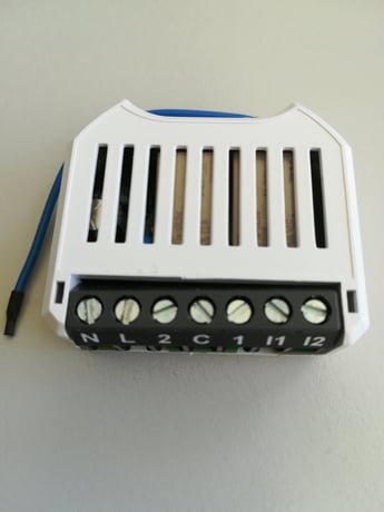
Product Image


1 - Heartbeat rate
A heartbeat notification is sent at this rateSize: 2 bytes
Default: 60
Minimum: 1
Maximum: 1440
Possible values
| From | To | Desription |
|---|---|---|
| 1 | 1440 | Heartbeat rate [min] |
2 - Full distance down drive time
Time the blind uses to drive from upper end position to the lower end position.Size: 2 bytes
Default: 0
Minimum: 0
Maximum: 30000
Possible values
| From | To | Desription |
|---|---|---|
| 0 | 30000 | Full distance down drive time [0.01s] |
3 - Full distance up drive time
Time the blind uses to drive from lower end position to the upper end position.Size: 2 bytes
Default: 0
Minimum: 0
Maximum: 30000
Possible values
| From | To | Desription |
|---|---|---|
| 0 | 30000 | Full distance up drive time [0.01s] |
4 - Time to move slat between horizontal and vertivcal
Time to move slat between horizontal and vertivcalSize: 2 bytes
Default: 120
Minimum: 0
Maximum: 500
Possible values
| From | To | Desription |
|---|---|---|
| 0 | 500 | Slat move time [0.01s] |
5 - Start position calibration
Start a positioning calibration. Used to start to measure time used by blind to move from one end position to the other.Size: 2 bytes
Default: 0
Minimum: 0
Maximum: 1
Possible values
| From | To | Desription |
|---|---|---|
| 0 | 0 | Position calibration is inactive / has ended |
| 1 | 1 | Start Position calibration / position calibration is active |
6 - Invert outputs
Normaly output 1 is used to drive blind upwards and output 2 to drive it downwards. When parameter is set to 1 output 1 drives blind downwards and output 2 upwards.Size: 2 bytes
Default: 0
Minimum: 0
Maximum: 1
Possible values
| From | To | Desription |
|---|---|---|
| 0 | 0 | Normal assignment of outputs |
| 1 | 1 | Inverted assignment of outputs |
7 - Min off time of outputs
When blind should change direction while running, the time defined in this parameter is used between stopping active direction output and starting oposite direction output.Size: 2 bytes
Default: 10
Minimum: 10
Maximum: 50
Possible values
| From | To | Desription |
|---|---|---|
| 10 | 50 | Minimum off time of one output before turning on other one [0.01s] |
8 - Key assignment local control
Digital inputs and Touch add-on may be used to control blinds locally. Different key pairs can be assigned to control blind to move up or down resp.Size: 2 bytes
Default: 0
Minimum: 0
Maximum: 6
Possible values
| From | To | Desription |
|---|---|---|
| 0 | 0 | Locol control of blinds disabled |
| 1 | 1 | Input 1 --> up, input 2 --> down |
| 2 | 2 | Input 1 --> down, input 2 --> up |
| 3 | 3 | Touch 2 --> up, touch 4 --> down |
| 4 | 4 | Touch 3 --> up, touch 5 --> down |
| 5 | 5 | Touch 2 --> left, touch 3 --> right |
| 6 | 6 | Touch 4 --> left, touch 5 --> right |
9 - Key hold time to move to end position
When key is hold shorter time than parameter value, movement stops, when key is released. If key is hold longer than parameter value, blind moves until reaching end position also when key is released.Size: 2 bytes
Default: 20
Minimum: 0
Maximum: 50
Possible values
| From | To | Desription |
|---|---|---|
| 0 | 50 | Key hold time to move to end position [0.1s] |
Manual inclusion (“Add”) 1. Activate the “Add” mode on your controller. 2. When 110 – 230 VAC is used, press a button connected to input I1 or I2 four times in quick succession to start include (“Add”). If a switch is used instead of the button, it must be changed accordingly eight times. 3. Alternatively, when 24 VDC is used, you can press the small lever (T) four times in quick succession with a pen to start “Add”. When the device is in the “Add” mode, the LED flashes green. When finished, the new status is: Add: The LED lights up briefly in green Remove: The LED lights up briefly in red
Manual exclusion (“Remove”) 1. Activate the “Remove” mode on your controller. 2. When 110 – 230 VAC is used, press a button connected to input I1 or I2 four times in quick succession to start exclude (“Remove”). If a switch is used instead of the button, it must be changed accordingly eight times. 3. Alternatively, when 24 VDC is used, you can press the small lever (T) four times in quick succession with a pen to start “Remove”. When finished, the new status is: Add: The LED lights up briefly in green Remove: The LED lights up briefly in red
Reset to factory default If the myTEM Radio Switch Dual Plus shows status “Add”, the “Remove” can be performed with any controller in the network or with the help of a new controller. However it is recommended to use the primary controller of the previous network unless it is no longer available or damaged. “Remove” deletes the memory chip, including all Z-Wave network and custom configuration settings.
The QR code is located on the side of the housing.
| Type | Value(s) |
|---|
| Group | Type |
|---|---|
| Power Management | Power status: Power has been applied |
| System | Heartbeat |