QUBINO
Luxy Smart Switch
ZMNKAD1
Color Switch
HW: 1 FW: 20.00:20.00
ZM5101
6.82.01
0x0159 (345)
0x0008 (8)
0x0052 (82)
ZC10-21017006
2021-01-28 12:54:51.573769
N/A
Enhanced 232 Slave
Always On Slave
Luxy Smart Switch is an innovative light switch that can illuminate your home in more than 16 million colors and can easily replace existing light switches.
Luxy Smart Switch is an innovative light source that gently illuminates in more than 16 million colors and easily fits into places of your light switch or socket. It can be used standalone, as ambient light, or as a smart home device. With an additional output, it can simply replace your existing light switch or can be used for powering IR panels, fans, water heaters, etc.
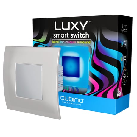
Product Image


1 - Parameter no. 1 – Relay contact type
Defines the contact type when open/closed contact. Values (size is 1-byte dec): • Default value 0 • 0 - NO (normally open) output type • 1 - NC (normally close) output typeSize: 1 byte
Default: 0
Minimum: 0
Maximum: 1
Possible values
| From | To | Desription |
|---|---|---|
| 0 | 0 | NO (normally open) output type |
| 1 | 1 | NC (normally close) output type |
3 - Parameter no 3. – turning off alarming
Values (size is 1-byte dec): • Default value 1 • 0 – only by z-wave command (basic set, switch multilevel set, switch multilevel start/stop level change, switch color set, switch color start/stop level change, notification report idle) • 1 – capacitive input (up, down, left, right) or z-wave command (basic set, switch multilevel set, switch multilevel start/stop level change, , switch color set, switch color start/stop level change, notification report idle)Size: 1 byte
Default: 1
Minimum: 0
Maximum: 1
Possible values
| From | To | Desription |
|---|---|---|
| 0 | 0 | only by z-wave command (basic set, switch multilevel set, switch multilevel start/stop level change, switch color set, switch color start/stop level change, notification report idle) |
| 1 | 1 | capacitive input (up, down, left, right) or z-wave command (basic set, switch multilevel set, switch multilevel start/stop level change, , switch color set, switch color start/stop level change, notification report idle) |
10 - Parameter no. 10. – auto on timer
Defines the time after which the device is turned to last known state. Values (size is 1-byte dec): • Default value 0 • 0 – disabled • 30 – 32535 = 30 – 32535 seconds after which the device turns onSize: 2 bytes
Default: 0
Minimum: 0
Maximum: 32525
Possible values
| From | To | Desription |
|---|---|---|
| 0 | 0 | disabled |
| 30 | 32525 | 30 – 32535 seconds after which the device turns on |
11 - Parameter no. 11. – auto off timer
Values (size is 2-byte dec): Defines the time after which the device is turned to last known state. • Default value 0 • 0 – disabled • 30 – 32535 = 30 – 32535 seconds after which the device turns offSize: 2 bytes
Default: 30
Minimum: 0
Maximum: 32525
Possible values
| From | To | Desription |
|---|---|---|
| 0 | 0 | disabled |
| 30 | 32525 | 30 – 32535 seconds after which the device turns off |
12 - Parameter no. 12. – auto on timer relay
Defines the time after which the device's relay is turned to last known state. Values (size is 2-byte dec): • Default value 0 • 0 – disabled • 30 – 32535 = 30 – 32535 seconds after which the device turns onSize: 2 bytes
Default: 30
Minimum: 0
Maximum: 32525
Possible values
| From | To | Desription |
|---|---|---|
| 0 | 0 | disabled |
| 30 | 32525 | 30 – 32535 seconds after which the device turns on |
13 - Parameter no. 13. – auto off timer relay
Defines the time after which the device's relay is turned to last known state. Values (size is 2-byte dec): • Default value 0 • 0 – disabled • 30 – 32535 = 30 – 32535 seconds after which the device turns offSize: 2 bytes
Default: 30
Minimum: 0
Maximum: 32525
Possible values
| From | To | Desription |
|---|---|---|
| 0 | 0 | disabled |
| 30 | 32525 | 30 – 32535 seconds after which the device turns off |
30 - Parameter no. 30. – restore state on power failure
Values (size is 1-byte dec): • Default value 1 • 1 – enabled (the device will restore state on power failure) • 0 – disabled (the device will not restore state on power failure and will remain off)Size: 1 byte
Default: 1
Minimum: 0
Maximum: 1
Possible values
| From | To | Desription |
|---|---|---|
| 1 | 1 | enabled (the device will restore state on power failure) |
| 0 | 0 | disabled (the device will not restore state on power failure and will remain off) |
31 - Parameter no. 31. – restore relay state on power failure
Values (size is 1-byte dec): • Default value 1 • 1 – enabled (the device will restore state on power failure) • 0 – disabled (the device will not restore state on power failure and will remain off)Size: 1 byte
Default: 1
Minimum: 0
Maximum: 1
Possible values
| From | To | Desription |
|---|---|---|
| 1 | 1 | enabled (the device will restore state on power failure) |
| 0 | 0 | disabled (the device will not restore state on power failure and will remain off) |
40 - Parameter no. 40 – Watt Power Consumption Reporting Threshold for Load
Choose by how much power consumption needs to increase or decrease to be reported. Values correspond to percentages so if 10 is set (by default), the device will report any power consumption changes of 10 % or more compared to the last reading. Values (size is 2-byte dec): • Default value 10 • 0 - Power consumption reporting disabled • 1 - 100 = 1 % - 100 % Power consumption reporting enabled. New value is reported only when Wattage in real time changes by more than the percentage value set in this parameter compared to the previous Wattage reading, starting at 1 % (the lowest value possible). NOTE: Power consumption needs to increase or decrease by at least 1 Watt to be reported, REGARDLESS of percentage set in this parameter.Size: 2 bytes
Default: 10
Minimum: 0
Maximum: 100
Possible values
| From | To | Desription |
|---|---|---|
| 0 | 0 | Power consumption reporting disabled |
| 1 | 100 | = 1 % - 100 % Power consumption reporting enabled. New value is reported only when Wattage in real time changes by more than the percentage value set in this parameter compared to the previous Wattage reading, starting at 1 % (the lowest value possible). NOTE: Power consumption needs to increase or decrease by at least 1 Watt to be reported, REGARDLESS of percentage set in this parameter. |
42 - Parameter no. 42 – Watt Power Consumption Reporting Time Threshold for Load
Set value refers to the time interval with which power consumption in Watts is reported (0 – 32535 seconds). If 300 is entered (by default), energy consumption reports will be sent to the gateway (hub) every 300 seconds (or 5 minutes). Values (size is 2-byte dec): • Default value 0 • 0 - Power consumption reporting disabled • 30 - 32535 = 30 - 32535 seconds. Power consumption reporting enabled. Report is sent according to time interval (value) set here.Size: 2 bytes
Default: 0
Minimum: 0
Maximum: 32525
Possible values
| From | To | Desription |
|---|---|---|
| 0 | 0 | Power consumption reporting disabled |
| 30 | 32525 | 30 - 32535 seconds. Power consumption reporting enabled. Report is sent according to time interval (value) set here |
60 - Parameter no. 60 – Lock touch for relay only
This parameter enables ONLY the touch functionality for closing/opening the relay meant for switching ON/OFF the connected light or any other connected load. See chapter 5.4 for additional information. Values (size is 1-byte dec): • Default value 0 • 0 – disabled • 1 – enabled (the user can switch ON/OFF the connected light or any other connected load by touching ANY button. Other functionalities (lighting mode, scenes, dimming and full white, inclusion/exclusion and reset) are unavailable until function disabled).Size: 1 byte
Default: 0
Minimum: 0
Maximum: 1
Possible values
| From | To | Desription |
|---|---|---|
| 0 | 0 | disabled |
| 1 | 1 | enabled (the user can switch ON/OFF the connected light or any other connected load by touching ANY button. Other functionalities (lighting mode, scenes, dimming and full white, inclusion/exclusion and reset) are unavailable until function disabled). |
70 - Parameter no. 70 - Overload safety switch
The function allows for turning off the controlled device in case of exceeding the defined power for more than 5 sec. Controlled device can be turned back on by capacitive antenna/s or sending a control frame. Values (size is 2-byte dec): • Default value 2300 • 0 = function not active • 1 – 2300 = 1 W – 2300 W ⓘ NOTE: This functionality is not an overload safety protection, please check chapter “Functionalities” for more details. In case of overload the following message will be send towards the controller: COMMAND_CLASS_NOTIFICATION_V5 The Alarm V1 type field set to 0x00 Notification Type 0x08 and 0x08 (Overload detected)Size: 2 bytes
Default: 1
Minimum: 0
Maximum: 2300
Possible values
| From | To | Desription |
|---|---|---|
| 0 | 0 | function not active |
| 1 | 2300 | 1 W – 2300 W |
1. Enable add/remove mode on your Z-Wave gateway (hub). 2. Connect the device to the power supply. 3. Make sure the device is within direct range of your Z-Wave gateway (hub). 4. Press once on button 3 – right. One press on button 4 – down for enabling full white. When full white is enabled, press, and hold button 3 – right, between 4 and 6 seconds. After 6 seconds, the device starts flashing green (1 second ON, 0.5 second OFF). Once the device receives node ID (after 10 seconds), it stops flashing and turns full green. The procedure is always available. Note: In case of S2 Security inclusion a dialog will appear prompting you to enter the corresponding PIN number (5 underlined digits) that are written on the module label and the label inserted in the packaging (check the example picture). IMPORTANT: The PIN code must not be lost.
1. Connect the device to the power supply. 2. Make sure the device is within direct range of your Z-Wave gateway (hub) or use a hand-held Z-Wave remote to perform exclusion. 3. Enable exclusion mode on your Z-Wave gateway (hub). 4. Press once on button 3 – right. One press on button 4 – down for enabling full white. When full white is enabled, press, and hold button 3 – right for 5 seconds. After 5 seconds, the device starts flashing red 1 second ON, 0.5 second OFF. Once the device loses node ID (after 10 seconds), it stops flashing and turns full red. The procedure is always available. NOTE: LEARN MODE state allows the device to receive network information from the controller.
1. Connect the device to the power supply 2. Press once on button 3 – right. One press on button 4 – down for enabling full white. When full white is enabled, press and hold button 5 – left for 10 seconds. After 10 seconds, the device starts flashing blue 1 second on, 0.5 second off. After 10 seconds the device stops flashing and turns full blue. The procedure is available always. By resetting the device, all custom parameters previously set on the device will return to their default values, and a node ID will be deleted. Use this reset procedure only when the gateway (hub) is missing or otherwise inoperable. NOTE: See extended manual for custom settings and parameters available for this device.
How to locate the DSK label on the product: When adding the Luxy Smart Switch to a Z-Wave network with a controller supporting Security 2 (S2), the PIN code of the Z-Wave Device Specific Key (DSK) is required. The unique DSK code is printed on the product label and a copy is inserted in the packaging, which must not be lost. Do not remove the DSK from the product. As a backup measure, use the label in the packaging. The first five digits of the key are highlighted or underlined to help the user identify the PIN code portion of the DSK text. The DSK is additionally represented with a QR Code. How to access the DSK via UI: SMARTSTART INCLUSION 1. Scan QR code on device label and add S2 DSK to Provisioning List in gateway (hub). 2. Connect the device to the power supply. 3. Make sure the device is within direct range of your Z-Wave gateway (hub. 4. Inclusion will be initiated automatically within few seconds of connection to the power supply and the device will automatically enrol in your network (when the device is excluded and connected to the power supply it automatically enters the LEARN MODE state). MANUAL INCLUSION 1. Enable add/remove mode on your Z-Wave gateway (hub). 2. Connect the device to the power supply. 3. Make sure the device is within direct range of your Z-Wave gateway (hub). 4. Press once on button 3 – right. One press on button 4 – down for enabling full white. When full white is enabled, press, and hold button 3 – right, between 4 and 6 seconds. After 6 seconds, the device starts flashing green (1 second ON, 0.5 second OFF). Once the device receives node ID (after 10 seconds), it stops flashing and turns full green. The procedure is always available. Note: In case of S2 Security inclusion a dialog will appear prompting you to enter the corresponding PIN number (5 underlined digits) that are written on the module label and the label inserted in the packaging (check the example picture). IMPORTANT: The PIN code must not be lost.
| Group | Type |
|---|---|
| Smoke Alarm | Alarm status: Smoke alarm test |
| Meter type |
|---|
| Gas Meter Consumption |