Zooz
Scenes Controller
ZEN32
Binary Switch
HW: 1 FW: 1.00
ZGM130
7.13.6
0x027A (634)
0xBB00 (47872)
0xBB08 (47880)
ZC12-21030205
2021-03-23 16:17:27.681853
N/A
Enhanced 232 Slave
Always On Slave
Use this multitasking Z-Wave Switch to control other devices in your network with 4 remote control buttons.
FEATURES: - Switch button: 15 A relay for Z-Wave on/off control - 4 remote control buttons: trigger scenes and control other devices in your Z-Wave network from this switch - NEW 700 series Z-Wave chip for better range and faster control - Direct 3-Way: works with regular on/off switches in a 3-way - Scene control: trigger actions with multi-tap (select hubs only) - Smart bulb mode: disable relay and control the light via Z-Wave - Adjustable LED indicator in 4 colors and 3 brightness levels - S2 Security and SmartStart for easier inclusion SPECS: - Model Number: ZEN32 - Z-Wave Signal Frequency: 908.42 MHz - Power: 120 VAC, 60 Hz - Maximum Load: 150W LED, 960W Incandescent, 1800W (15A) Resistive, 3A motor (DON’T use with receptacles) - Range: Up to 500 feet line of sight - Operating Temperature: 32-104° F (0-40° C) - Installation and Use: Indoor only
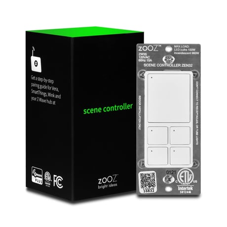
Product Image


1 - LED Indicator mode for relay
Choose if you want the LED indicator to turn on when the relay is on or off, or if you want it to remain on or off at all times.Size: 1 byte
Default: 0
Minimum: 0
Maximum: 3
Possible values
| From | To | Desription |
|---|---|---|
| 0 | 0 | LED on when relay off, LED off when relay on (default) |
| 1 | 1 | LED on when relay on, LED off when relay off |
| 2 | 2 | LED always off |
| 3 | 3 | LED always on |
2 - LED Indicator mode for Button 1
Choose if you want the LED indicator to turn on when Button 1 is on or off, or if you want it to remain on or off at all times.Size: 1 byte
Default: 0
Minimum: 0
Maximum: 3
Possible values
| From | To | Desription |
|---|---|---|
| 0 | 0 | LED on when dimmer off, LED off when dimmer on (default) |
| 1 | 1 | LED on when dimmer on, LED off when dimmer off |
| 2 | 2 | LED always off |
| 3 | 3 | LED always on |
3 - LED Indicator mode for Button 2
Choose if you want the LED indicator to turn on when Button 2 is on or off, or if you want it to remain on or off at all times.Size: 1 byte
Default: 0
Minimum: 0
Maximum: 3
Possible values
| From | To | Desription |
|---|---|---|
| 0 | 0 | LED on when dimmer off, LED off when dimmer on (default) |
| 1 | 1 | LED on when dimmer on, LED off when dimmer off |
| 2 | 2 | LED always off |
| 3 | 3 | LED always on |
4 - LED Indicator mode for Button 3
Choose if you want the LED indicator to turn on when Button 3 is on or off, or if you want it to remain on or off at all times.Size: 1 byte
Default: 0
Minimum: 0
Maximum: 3
Possible values
| From | To | Desription |
|---|---|---|
| 0 | 0 | LED on when dimmer off, LED off when dimmer on (default) |
| 1 | 1 | LED on when dimmer on, LED off when dimmer off |
| 2 | 2 | LED always off |
| 3 | 3 | LED always on |
5 - LED Indicator mode for Button 4
Choose if you want the LED indicator to turn on when Button 4 is on or off, or if you want it to remain on or off at all times.Size: 1 byte
Default: 0
Minimum: 0
Maximum: 3
Possible values
| From | To | Desription |
|---|---|---|
| 0 | 0 | LED on when dimmer off, LED off when dimmer on (default) |
| 1 | 1 | LED on when dimmer on, LED off when dimmer off |
| 2 | 2 | LED always off |
| 3 | 3 | LED always on |
6 - LED Indicator color for relay
Choose the color of the LED indicator for the relay.Size: 1 byte
Default: 0
Minimum: 0
Maximum: 3
Possible values
| From | To | Desription |
|---|---|---|
| 0 | 0 | white |
| 1 | 1 | blue |
| 2 | 2 | green |
| 3 | 3 | red |
7 - LED Indicator color for Button 1
Choose the color of the LED indicator for Button 1.Size: 1 byte
Default: 0
Minimum: 0
Maximum: 3
Possible values
| From | To | Desription |
|---|---|---|
| 0 | 0 | white |
| 1 | 1 | blue |
| 2 | 2 | green |
| 3 | 3 | red |
8 - LED Indicator color for Button 2
Choose the color of the LED indicator for Button 2.Size: 1 byte
Default: 0
Minimum: 0
Maximum: 3
Possible values
| From | To | Desription |
|---|---|---|
| 0 | 0 | white |
| 1 | 1 | blue |
| 2 | 2 | green |
| 3 | 3 | red |
9 - LED Indicator color for Button 3
Choose the color of the LED indicator for Button 3.Size: 1 byte
Default: 0
Minimum: 0
Maximum: 3
Possible values
| From | To | Desription |
|---|---|---|
| 0 | 0 | white |
| 1 | 1 | blue |
| 2 | 2 | green |
| 3 | 3 | red |
10 - LED Indicator color for Button 4
Choose the color of the LED indicator for Button 4.Size: 1 byte
Default: 0
Minimum: 0
Maximum: 3
Possible values
| From | To | Desription |
|---|---|---|
| 0 | 0 | white |
| 1 | 1 | blue |
| 2 | 2 | green |
| 3 | 3 | red |
11 - LED Indicator brightness for relay
Choose the LED indicator's brightness level for the relay.Size: 1 byte
Default: 1
Minimum: 0
Maximum: 2
Possible values
| From | To | Desription |
|---|---|---|
| 0 | 0 | white |
| 1 | 0 | medium (60%) |
| 2 | 0 | low (30%) |
12 - LED Indicator brightness for Button 1
Choose the LED indicator's brightness level for Button 1.Size: 1 byte
Default: 1
Minimum: 0
Maximum: 2
Possible values
| From | To | Desription |
|---|---|---|
| 0 | 0 | bright (100%) |
| 1 | 1 | medium (60%) |
| 2 | 2 | low (30%) |
13 - LED Indicator brightness for Button 2
Choose the LED indicator's brightness level for Button 2.Size: 1 byte
Default: 1
Minimum: 0
Maximum: 2
Possible values
| From | To | Desription |
|---|---|---|
| 0 | 0 | bright (100%) |
| 1 | 1 | medium (60%) |
| 2 | 2 | low (30%) |
14 - LED Indicator brightness for Button 3
Choose the LED indicator's brightness level for Button 3.Size: 1 byte
Default: 1
Minimum: 0
Maximum: 2
Possible values
| From | To | Desription |
|---|---|---|
| 0 | 0 | bright (100%) |
| 1 | 1 | medium (60%) |
| 2 | 2 | low (30%) |
15 - LED Indicator brightness for Button 4
Choose the LED indicator's brightness level for Button 4.Size: 1 byte
Default: 1
Minimum: 0
Maximum: 2
Possible values
| From | To | Desription |
|---|---|---|
| 0 | 0 | bright (100%) |
| 1 | 1 | medium (60%) |
| 2 | 2 | low (30%) |
16 - Auto Turn-Off Timer for Relay
Use this parameter to enable or disable the auto turn-off timer function (the time after which you want the switch to automatically turn off once it has been turned on).Size: 4 bytes
Default: 0
Minimum: 0
Maximum: 65535
Possible values
| From | To | Desription |
|---|---|---|
| 0 | 0 | disabled |
| 1 | 65535 | minutes |
17 - Auto Turn-ON Timer for Relay
Use this parameter to enable or disable the auto turn-on timer function (the time after which you want the switch to automatically turn on once it has been turned off).Size: 4 bytes
Default: 0
Minimum: 0
Maximum: 65535
Possible values
| From | To | Desription |
|---|---|---|
| 0 | 0 | disabled |
| 1 | 65535 | minutes |
18 - State After Power Failure
Set the on off status for the switch after power failure.Size: 1 byte
Default: 0
Minimum: 0
Maximum: 2
Possible values
| From | To | Desription |
|---|---|---|
| 0 | 0 | remembers and restores on/off status after power failure (default) |
| 1 | 1 | Relay and buttons forced to off after power failure |
| 2 | 2 | Relay and buttons forced to on after power failure |
19 - Disable / Enable Control on the Relay
Enable or disable paddle on/off control (aka disable the relay). If disabled, you’ll only be able to control the connected light via Z-Wave. Scenes and other functionality will still be available through buttons.Size: 1 byte
Default: 1
Minimum: 0
Maximum: 2
Possible values
| From | To | Desription |
|---|---|---|
| 0 | 0 | Disable local / physical control (from the button), enable Z-Wave control |
| 1 | 1 | 1 – Enable local / physical control (from the button), enable Z-Wave control (default) |
| 2 | 2 | Disable local / physical control (from the button), disable Z-Wave control |
20 - Relay Behavior with Disabled Local / Z-Wave Control
Set reporting behavior for disabled physical control.Size: 1 byte
Default: 1
Minimum: 0
Maximum: 1
Possible values
| From | To | Desription |
|---|---|---|
| 0 | 0 | report on/off status when button is pressed and change LED indicator status if Parameter 19 is set to value 0 or 2 |
| 1 | 1 | DON’T report on/off status when button is pressed and DON’T change LED indicator status if Parameter 19 is set to value 0 or 2 (but the relay will always send central scene command) |
INCLUSION 1. Initiate inclusion (pairing) in the app (or web interface). 2. TAP THE SWITCH BUTTON 3 TIMES QUICKLY if using traditional Z-Wave inclusion. 3. The LED indicator will blink blue to signal communication and turn green for 3 seconds if inclusion is successful or turn red for 3 seconds if the pairing attempt fails.
EXCLUSION 1. Bring your Z-Wave gateway (hub) close to the switch if possible 2. Put the Z-Wave hub into exclusion mode (not sure how to do that? [email protected]) 3. TAP THE SWITCH BUTTON 3 TIMES QUICKLY (the LED indicator will start blinking blue) 4. Your hub will confirm exclusion, the LED indicator on the switch will turn green for 3 seconds, and the device will disappear from your controller's device list reset
If your primary controller is missing or inoperable, you may need to reset the device to factory settings. To reset the switch, press and hold the switch button for 20 seconds until the LED indicator starts flashing red. Release the button, and immediately aer, tap remote button 1 once to complete the reset. The LED indicators on all buttons will flash red to confirm a successful reset.
- Direct 3-Way Solution - 4 Remote Control Buttons for Scene Control - Multicolor LED Indicators
Scan the QR code / enter the 5-digit DSK > visual indication where to find the code on the product (in the lower left corner of the metal plate on the switch)
| Type | Value(s) |
|---|