Zooz
UNIVERSAL RELAY
ZEN17
Binary Switch
HW: 1 FW: 1.00
ZGM130
7.13.6
0x027A (634)
0xBB00 (47872)
0xBB0A (47882)
ZC12-21030204
2021-03-23 16:19:19.179322
N/A
Enhanced 232 Slave
Always On Slave
2 Dry Contact NO-C-NC Relays with Adjustable 12-24 and Dry Contact Inputs: Add Z-Wave to Most Analog Devices
FEATURES: - Powerful dry contact NO/NC relays to control loads up to 20 A for NO - Perfect for DC motors, pumps, commercial gates, or HVAC equipment - Control up to 2 connected loads independently or together - Z-Wave or optional wall switch control (toggle or momentary type) - Monitor inputs independently from output control - Built-in timers for each relay to simplify automation - Built-in Z-Wave Plus signal repeater to extend network range - Powered by 12-24 V DC/AC or USB C port for easy set-up - Wall mounting and minimal design for clean installation - NEW 700 Z-Wave chip, S2 security, and SmartStart SPECS: - Model Number: ZEN17 - Z-Wave Signal Frequency: 908.42 MHz - Power: 12-24 V DC/AC or USB C (DON’T use laptop / tablet chargers) - Maximum Load: NO relays: 20 A, NC relays: 10 A - Inputs: dry contact or 12-24 V AC/DC (use 1 input type at a time!) - Range: Up to 200 feet line of sight - Operating Temperature: 32-104° F (0-40° C) - Installation and Use: Indoor only
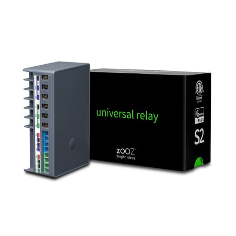
Product Image


1 - On Off Status After Power Failure
Set the on off status for the relays after power failure.Size: 1 byte
Default: 1
Minimum: 0
Maximum: 4
Possible values
| From | To | Desription |
|---|---|---|
| 0 | 0 | ALL relays forced to OFF (regardless of state prior to power outage) |
| 1 | 1 | ALL relays remember and restore on/off status after power failure (default) |
| 2 | 2 | ALL relays forced to ON (regardless of state prior to power outage) |
| 3 | 3 | Relay 1 remembers and restores on/off status after power failure, Relay 2 forced to ON |
| 4 | 4 | Relay 2 remembers and restores on/off status after power failure, Relay 1 forced to ON. |
2 - Input Type for Relay 1 (S1)
Choose the wall switch or input type you want to connect to the S1 C terminals. Press and hold the Z-Wave button for 5 seconds to change to garage mode manually. IMPORTANT: If you set this parameter to value 4-10, you’ll need to exclude and re-include the device (without changing any settings) so that a child device is created for the input of your choice!Size: 1 byte
Default: 2
Minimum: 0
Maximum: 10
Possible values
| From | To | Desription |
|---|---|---|
| 0 | 0 | momentary for lights only |
| 1 | 1 | toggle switch (light on when the switch is toggled up, light off when the switch is toggled down); |
| 2 | 2 | toggle switch (state changes whenever the switch is toggled) |
| 3 | 3 | garage door (momentary mode for Z-Wave control) |
| 4 | 4 | leak alarm (water sensor) |
| 5 | 5 | heat alarm |
| 6 | 6 | motion alert |
| 7 | 7 | open/close alert (door sensor) |
| 8 | 8 | CO alarm |
| 9 | 9 | CO2 alarm |
| 10 | 10 | on/off report (dry contact switch/sensor) |
3 - Input Type for Relay 2 (S2)
Choose the wall switch or input type you want to connect to the S2 C terminals. Click twice, holding the Z-Wave button for 5 seconds the second time to change to garage mode manually. IMPORTANT: If you set this parameter to value 4-10, you’ll need to exclude and re-include the device (without changing any settings) so that a child device is created for the input of your choice!Size: 1 byte
Default: 2
Minimum: 0
Maximum: 10
Possible values
| From | To | Desription |
|---|---|---|
| 0 | 0 | momentary for lights only |
| 1 | 1 | toggle switch (light on when the switch is toggled up, light off when the switch is toggled down) |
| 2 | 2 | toggle switch (state changes whenever the switch is toggled) |
| 3 | 3 | garage door (momentary mode for Z-Wave control) |
| 4 | 4 | leak alarm (water sensor) |
| 5 | 5 | heat alarm |
| 6 | 6 | motion alert |
| 7 | 7 | open/close alert (door sensor) |
| 8 | 8 | CO alarm |
| 9 | 9 | CO2 alarm |
| 10 | 10 | on/off report (dry contact switch/sensor) |
5 - LED Indicator Control
Choose if you want the LED indicator to turn on when any of the relays are on or if all of them are off, or if you want it to remain on or off at all times.Size: 1 byte
Default: 0
Minimum: 0
Maximum: 3
Possible values
| From | To | Desription |
|---|---|---|
| 0 | 0 | LED indicator is on when ALL of the relays are off, LED indicator is off when any of the relays is on (default); |
| 1 | 1 | LED indicator is on when any of the relays is on, LED indicator is off when ALL of the relays are off; |
| 2 | 2 | LED indicator is always OFF; |
| 3 | 3 | LED indicator is always ON |
6 - Auto Turn-Off Timer for Relay 1
Use this parameter to set the time after which you want the device connected to Relay 1 to automatically turn off once it has been turned on. The number entered as value corresponds to the number of minutes, seconds, or hours (set the unit in Par. 15).Size: 4 bytes
Default: 0
Minimum: 0
Maximum: 65535
Possible values
| From | To | Desription |
|---|---|---|
| 0 | 0 | disabled |
| 1 | 65535 | minutes/seconds/hours |
7 - Auto Turn-On Timer for Relay 1
Use this parameter to set the time after which you want the device connected to Relay 1 to automatically turn on once it has been turned off. The number entered as value corresponds to the number of minutes, seconds, or hours (set the unit in Par. 16).Size: 4 bytes
Default: 0
Minimum: 0
Maximum: 65535
Possible values
| From | To | Desription |
|---|---|---|
| 0 | 0 | disabled |
| 1 | 65535 | minutes/seconds/hours |
8 - Auto Turn-Off Timer for Relay 2
Use this parameter to set the time after which you want the device connected to Relay 2 to automatically turn off once it has been turned on. The number entered as value corresponds to the number of minutes, seconds, or hours (set the unit in Par. 17).Size: 4 bytes
Default: 0
Minimum: 0
Maximum: 65535
Possible values
| From | To | Desription |
|---|---|---|
| 0 | 0 | disabled |
| 1 | 65535 | minutes/seconds/hours |
9 - Auto Turn-On Timer for Relay 2
Use this parameter to set the time after which you want the device connected to Relay 2 to automatically turn on once it has been turned off. The number entered as value corresponds to the number of minutes, seconds, or hours (set the unit in Par. 18).Size: 4 bytes
Default: 0
Minimum: 0
Maximum: 65535
Possible values
| From | To | Desription |
|---|---|---|
| 0 | 0 | disabled |
| 1 | 65535 | minutes/seconds/hours |
10 - Input Trigger for Relay 1
Choose if you’d like the connected input (switch) on S1 C / VC C to trigger the load connected to R1 or if you want to use the input reports for monitoring only and separate the output from the input.Size: 1 byte
Default: 1
Minimum: 0
Maximum: 1
Possible values
| From | To | Desription |
|---|---|---|
| 0 | 0 | input trigger disabled |
| 1 | 1 | input trigger enabled (default) |
11 - Input Trigger for Relay 2
Choose if you’d like the connected input (switch) on S2 C / VC C to trigger the load connected to R2 or if you want to use the input reports for monitoring only and separate the output from the input.Size: 1 byte
Default: 1
Minimum: 0
Maximum: 1
Possible values
| From | To | Desription |
|---|---|---|
| 0 | 0 | input trigger disabled |
| 1 | 1 | input trigger enabled (default) |
15 - Auto Turn-Off Timer Unit for Relay 1
Choose between seconds, minutes, and hours as the unit for the auto turnoff timer for Relay 1.Size: 1 byte
Default: 0
Minimum: 0
Maximum: 2
Possible values
| From | To | Desription |
|---|---|---|
| 0 | 0 | minutes |
| 1 | 1 | seconds |
| 2 | 2 | hours |
16 - Auto Turn-On Timer Unit for Relay 1
Choose between seconds, minutes, and hours as the unit for the auto turn on timer for Relay 1.Size: 1 byte
Default: 0
Minimum: 0
Maximum: 2
Possible values
| From | To | Desription |
|---|---|---|
| 0 | 0 | minutes |
| 1 | 1 | seconds |
| 2 | 2 | hours |
17 - Auto Turn-Off Timer Unit for Relay 2
Choose between seconds, minutes, and hours as the unit for the auto turn off timer for Relay 2.Size: 1 byte
Default: 0
Minimum: 0
Maximum: 2
Possible values
| From | To | Desription |
|---|---|---|
| 0 | 0 | minutes |
| 1 | 1 | seconds |
| 2 | 2 | hours |
18 - Auto Turn-On Timer Unit for Relay 2
Choose between seconds, minutes, and hours as the unit for the auto turn on timer for Relay 2.Size: 1 byte
Default: 0
Minimum: 0
Maximum: 2
Possible values
| From | To | Desription |
|---|---|---|
| 0 | 0 | minutes |
| 1 | 1 | seconds |
| 2 | 2 | hours |
24 - DC Motor Mode
Sync R1 and R2 together to prevent them from being activated at the same time.Size: 1 byte
Default: 0
Minimum: 0
Maximum: 1
Possible values
| From | To | Desription |
|---|---|---|
| 0 | 0 | DC motor mode disabled (relays will activate whenever they're triggered) |
| 1 | 1 | DC motor mode enabled (relay will check the status of the other relay aer being triggered and will shut the other relay off before activating so that only one of the relays is on at the same time) |
INCLUSION 1. Initiate inclusion (pairing) in the app (or web interface). 2. TAP THE Z-WAVE BUTTON 3 TIMES QUICKLY if using traditional Z-Wave inclusion. 3. The LED indicator will blink to signal communication and remain on for 2 seconds to confirm inclusion.
1. Bring your Universal Relay close to the Z-Wave hub and power it 2. Put the Z-Wave hub into exclusion mode 3. Click the Z-Wave button 3 times quickly 4. Your hub will confirm exclusion and the Universal Relay will disappear from your controller's device list
If your primary controller is missing or inoperable, you may need to reset the device to factory settings. To complete the reset process manually, click the Z-Wave button 4 times quickly, the LED indicator will light up, then quickly click the Z-Wave button 4 times again. The LED indicator will flash 3 times to confirm successful reset and will then turn off.
Under Z-Wave Control > Add device
Additional devices created when input type set to security sensor (Parameters 2-3 set to values 4-10).
IMPORTANT: If you set this parameter to value 4-10, you’ll need to exclude and re-include the device (without changing any settings) so that a child device is created for the input of your choice!
| Type | Value(s) |
|---|
| Group | Type |
|---|---|
| Smoke Alarm |
|
| CO Alarm |
|
| CO2 Alarm |
|
| Heat Alarm |
|
| Water Alarm |
|
| Access Control |
|