Schlage
J-Series by Schlage Z-Wave Keypad Deadbolt
JBE109
Lock
HW: 3 FW: 1.09:01.13
ZGM130
7.11.1
0x003B (59)
0x0004 (4)
0x2109 (8457)
ZC12-21040221
2021-04-20 11:27:55.81315
N/A
Enhanced 232 Slave
Listening Sleeping Slave
Yes
The J-Series by Schlage Z-Wave Deadbolt combines advanced features and compatibility with home automation or security systems, so you can control your lock from anywhere using your smartphone.
The J-Series by Schlage Z-Wave Deadbolt combines advanced features and compatibility with your home automation or security system, allowing you to control your lock from anywhere and freeing you from the hassles of lost keys, getting locked out, or hiding a spare for friends and family. The lock comes preprogrammed with two access codes and can hold up to 30 unique codes for family members and trusted friends. The J-Series by Schlage Z-Wave Deadbolt is battery-powered with a low battery warning that gives you weeks of advanced notice before it runs out. With guaranteed fit on standard doors, it’s easy for homeowners to install in minutes with just a screwdriver. The touchscreen continues to work in the event of a power outage, so you don’t have to worry about getting locked out – plus, a back-up key is included with the lock for peace of mind. The J-Series by Schlage Z-Wave Deadbolt incorporates Z-Wave Plus S2 technology, an enhanced security protocol that features an additional layer of AES encryption of wireless signals. The Z-Wave technology allows you to integrate your exterior door locks with other Z-Wave smart home devices, such as cameras, motion detectors, lights and thermostats, bringing the safety, simplicity and style of Schlage to your smart home.
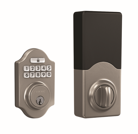
Product Image


3 - BEEPER
CONFIG ENABLE SND FF ELSE 00Size: 1 byte
Default: 255
Minimum: 0
Maximum: 255
Possible values
| From | To | Desription |
|---|---|---|
| 0 | 0 | Disable Beeper |
| 255 | 255 | Enable Beeper |
4 - VACATION_MODE
CONFIG ENABLE SND FF ELSE 00Size: 1 byte
Default: 0
Minimum: 0
Maximum: 255
Possible values
| From | To | Desription |
|---|---|---|
| 0 | 0 | Disable Vacation Mode |
| 255 | 255 | Enable Vacation Mode |
5 - LOCK_AND_LEAVE
CONFIG ENABLE SND FF ELSE 00Size: 1 byte
Default: 255
Minimum: 0
Maximum: 255
Possible values
| From | To | Desription |
|---|---|---|
| 0 | 0 | Disable Lock & Leave |
| 255 | 255 | Enable Lock & Leave |
6 - USER_SLOT_BIT_FIELD
GET USER SLOT OCCUPIEDSize: 4 bytes
Default: 0
Minimum: 0
Maximum: 1073741823
Possible values
| From | To | Desription |
|---|---|---|
| 1 | 1 | User Slots 8 – 1 (MSB – LSB) 8,7,6,5,4,3,2,1 |
| 2 | 2 | User Slots 16 – 9 (MSB – LSB) 16,15,14,13,12,11,10,9 |
| 3 | 3 | User Slots 24 – 17 (MSB – LSB) 24,23,22,21,20,19,18,17 |
| 4 | 4 | User Slots 30 – 25 (MSB – LSB) X,X,30,29,28,27,26,25 |
15 - AUTO_LOCK
CONFIG ENABLE SND FF ELSE 00Size: 1 byte
Default: 0
Minimum: 0
Maximum: 255
Possible values
| From | To | Desription |
|---|---|---|
| 0 | 0 | Disable Auto Lock |
| 255 | 255 | Enable Auto Lock |
16 - USER_CODE_PIN_LENGTH
CONFIG PINLEN SND VAL 4 TO 8Size: 1 byte
Default: 4
Minimum: 4
Maximum: 8
Possible values
| From | To | Desription |
|---|---|---|
| 4 | 8 | User Code PIN length, a value between 4 and 8 (default 4) |
One-button Add lock to Z-Wave Network (Inclusion) 1. Place your home automation system or panel into the “Add” or Inclusion Mode (Refer to the respective documentation for that specific home automation system or panel device for details). 2. Remove the battery cover of the deadbolt. 3. Press then release the button on the PCB. 4. An LED will flash amber indicating the “Add” or Inclusion process is in progress. • If the Security Scheme is Security 2 (S2), verify the DSK of the lock at the Z-Wave Controller. The PIN Code portion of the Z-Wave DSK will be needed. 5. When a green LED turns ON, the “Add” or Inclusion has completed successfully. 6. If a red LED turns ON, try repeating steps 1-3 Interactive Instruction for Add https://instructions.allegion.com/instr/86/2543
One-button Remove lock from Z-Wave Network (Exclusion) 1. Place your home automation system or panel into the “Remove” or Exclusion Mode (Refer to the respective documentation for that specific home automation system or panel device for details). 2. Remove the battery cover of the deadbolt. 3. Press then release the button on the PCB. 4. An LED will flash amber indicating the “Remove” or Exclusion process is in progress. 5. When a green LED flashes 3 times, the “Remove” or Exclusion process is completed successfully. 6. If a red LED turns ON, try repeating steps 1-3 Interactive Instruction for Remove https://instructions.allegion.com/instr/86/258
N/A
1. Press and hold the enrollment button. The led will light solid amber. 2. After about 8 seconds of holding the button, the amber light will turn off. Release the button. Successful FDR is indicated by 3 long green blinks and 3 long beeps. 3. You must enter a valid user code. Lock will enter auto-handing routine, locking and unlocking several times. Auto-handing is complete when lock movement stops.
User Guide Page 2
| Type | Value(s) |
|---|
| Group | Type |
|---|---|
| Access Control |
|
| Power Management |
|