Minoston
Smart On/Off Toggle Switch
MS12ZS
Binary Switch
HW: 1 FW: 1.00
ZGM130
7.13.6
0x0312 (786)
0xEE00 (60928)
0xEE03 (60931)
ZC12-21040211
2021-04-01 15:43:27.0147
N/A
Enhanced 232 Slave
Always On Slave
In-Wall Smart Switch design features a housing depth that is up to 20 percent smaller than the previous Z-Wave models. This reduced size coupled with the elimination of heat taps provides a better fit in older style boxes and multi-gang configurations.
In-Wall Smart Switch design features a housing depth that is up to 20 percent smaller than the previous Z-Wave models. This reduced size coupled with the elimination of heat taps provides a better fit in older style boxes and multi-gang configurations. SimpleWire technology allows line and load to automatically be configured with auto-sensing line-load terminals. All of this is coupled with Z-Wave S2 and SmartStart allows for effortless installation while being safer than ever!
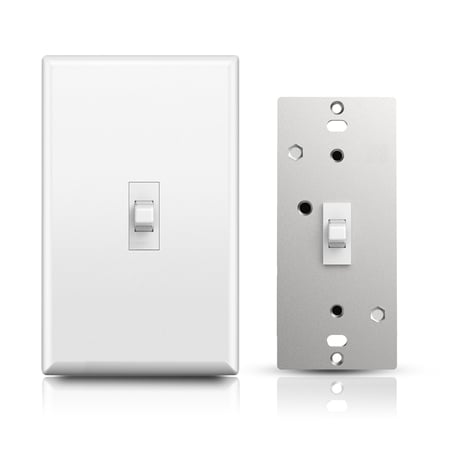
Product Image


1 - KeyFunction
Parameter=1,Size=1, Value=0 Up Button: On Down Button: Off Value=1 Up Button: Off Down Button: On Value=2 Up Button: On/Off Down Button: On/OffSize: 1 byte
Default: 0
Minimum: 0
Maximum: 2
Possible values
| From | To | Desription |
|---|---|---|
| 0 | 0 | Up Button ON,Down Button OFF |
| 1 | 1 | Up Button OFF,Down Button ON |
| 2 | 2 | Up Button ON/OFF,Down Button ON/OFF |
2 - LED Indicator
Parameter=2,Size=1 Value=0 On when Off and Off when On Value=1 On when On and Off when Off Value=2 Always Off Value=3 Always OnSize: 1 byte
Default: 0
Minimum: 0
Maximum: 3
Possible values
| From | To | Desription |
|---|---|---|
| 0 | 0 | On when Off and Off when On |
| 1 | 1 | On when On and Off when Off |
| 2 | 2 | Always OFF |
| 3 | 3 | Always ON |
3 - Auto Turn-Off Timer
Parameter=3,Size=4, Value=0 timer disabled (default); Values: 1 – 65535 (minutes);Size: 4 bytes
Default: 0
Minimum: 0
Maximum: 65535
Possible values
| From | To | Desription |
|---|---|---|
| 0 | 65535 | Auto Turn-Off Timer |
5 - Auto Turn-On Timer
Parameter=5,Size=1, Value=0 timer disabled (default); Values: 1 – 65535 (minutes);Size: 4 bytes
Default: 0
Minimum: 0
Maximum: 65535
Possible values
| From | To | Desription |
|---|---|---|
| 0 | 65535 | Auto Turn-On Timer |
8 - Restores state after power failure
Parameter=8,Size=1, Value=0 output off Value=1 output on Value=2 out put the state after powerSize: 1 byte
Default: 2
Minimum: 0
Maximum: 2
Possible values
| From | To | Desription |
|---|---|---|
| 0 | 0 | Output OFF |
| 1 | 1 | Output ON |
| 2 | 2 | out put the state after power |
9 - Enable or Disable Scene
Parameter=9,Size=1, Value=0 disable Value=1 enableSize: 1 byte
Default: 0
Minimum: 0
Maximum: 1
Possible values
| From | To | Desription |
|---|---|---|
| 0 | 0 | disable |
| 1 | 1 | enable |
11 - Enable or Disable OutPut control
Parameter=11,Size=1,Value=0 disable local button and External Switch control enable Z-Wave control Value=1 enable local button and External Switch control enable Z-Wave control Value = 2 disable local button and External Switch controlSize: 1 byte
Default: 1
Minimum: 0
Maximum: 2
Possible values
| From | To | Desription |
|---|---|---|
| 0 | 0 | disable local button and External Switch control enable Z-Wave conrol |
| 1 | 1 | enable local button and External Switch control enable Z-Wave control |
| 2 | 2 | disable local button and External Switch control |
12 - external switch type
Parameter=12, Size=1, Value=0 toggle switch(device changes status when switch changes status)(default); Value=1 momentary switchSize: 1 byte
Default: 0
Minimum: 0
Maximum: 1
Possible values
| From | To | Desription |
|---|---|---|
| 0 | 0 | toggle switch (device changes status when switch changes status) |
| 1 | 1 | momentary switch |
13 - Behavior when Output control disabled
Parameter 13 Size=1,Value=0 report on/off status and change LED indicator when upper or lower paddle is pressed and Parameter 11 is set to value 0 or 2 (output control disabled). Value=1 DON’t report on/off status or change LED indicator when upper or lower paddle is pressed and Parameter 11 is set to value 0 or 2 (output control disabled). Default = 0Size: 1 byte
Default: 0
Minimum: 0
Maximum: 1
Possible values
| From | To | Desription |
|---|---|---|
| 0 | 0 | report on/off status and change LED indicator when upper or lower paddle is pressed and Parameter 11 is set to value 0 or 2 (output control disabled) |
| 1 | 1 | DON’t report on/off status or change LED indicator when upper or lower paddle is pressed and Parameter 11 is set to value 0 or 2 (output control disabled). |
14 - LED Indicator Color
Parameter=14,Size=1, Value=0 White Value=1 Blue Value=2 Green Value=3 RedSize: 1 byte
Default: 1
Minimum: 0
Maximum: 3
Possible values
| From | To | Desription |
|---|---|---|
| 0 | 0 | White |
| 1 | 1 | Blue |
| 2 | 2 | Green |
| 3 | 3 | Red |
15 - LED Indicator Brightness
Parameter=15,Size=1, Value=0 Bright (100%) Value=1 Medium (60%) Value=2 Low (30%)Size: 1 byte
Default: 1
Minimum: 0
Maximum: 2
Possible values
| From | To | Desription |
|---|---|---|
| 0 | 0 | Bright (100%) |
| 1 | 1 | Medium (60%) |
| 2 | 2 | Low (30%) |
16 - Association reports
Parameter=16,Size=1 Values: 0 – Z-Wave control:Binary switch report Manual control: Basic set report 1 – Z-Wave control:Binary switch report Manual control: Binary switch reportSize: 1 byte
Default: 1
Minimum: 0
Maximum: 1
Possible values
| From | To | Desription |
|---|---|---|
| 0 | 0 | Z-Wave control:Binary switch report Manual control: Basic set report |
| 1 | 1 | Z-Wave control:Binary switch report Manual control: Binary switch report |
The device support two methods of inclusion,When using a Z-Wave Plus™ certified controller choose Network Wide Inclusion or SmartStart, Network Wide Inclusion To A Z-Wave™ Network 1,Refer to your primary controller instructions to process the inclusion / exclusion setup procedure. 2,When prompted by your primary controller, click the Up or Down button three times in one second.
The device support two methods of inclusion,When using a Z-Wave Plus™ certified controller choose Network Wide Inclusion or SmartStart, Network Wide Inclusion To A Z-Wave™ Network 1,Refer to your primary controller instructions to process the inclusion / exclusion setup procedure. 2,When prompted by your primary controller, click the Up or Down button three times in one second.
Press and hold lower paddle for 10 seconds,then LED starts blinking, release paddle and within 2 seconds,click lower paddle 5 times (Node:Please use this procedure only when the network primary controller is missing or otherwise inoperable.)
The device is compatible with SmartStart SmartStart enabled products can be added into a Z-Wave™ network by scanning the Z-Wave QR Code found on the top of the outlet or the back of the box with a controller providing SmartStart inclusion.No further action is required and the SmartStart product will be added automatically within 10 minutes of being switched on and in the network vicinity. QR CODE the QR code are sticked to the side of the case,DSK is included in the QR code. DSK The DSK code can be found on the DSK label which is attached on the packaging box.
| Type | Value(s) |
|---|