HomeSeer
Smart In Wall Dimmer
HS-WX300
Multilevel Switch
HW: 1 FW: 1.11
ZGM130
7.15.2
0x000C (12)
0x4447 (17479)
0x4036 (16438)
ZC12-21070246
2021-06-30 14:20:04.010753
N/A
Enhanced 232 Slave
Always On Slave
HS-WX300 is a Z-Wave™ in-wall light switch that may be configured to operate as either a dimmer switch or an on/off switch.
HS-WX300 is a Z-Wave™ in-wall light switch that may be configured to operate as either a dimmer switch or an on/off switch. It may be installed with or without a neutral wire and it works with both wired and wireless companion switches in 3-way circuit configurations. This switch has been designed, tested and certified for use in the United States and Canada.
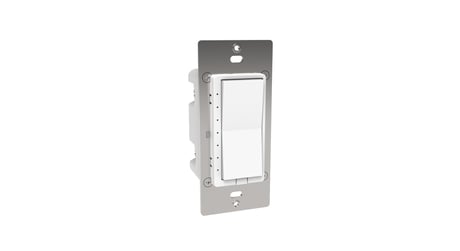
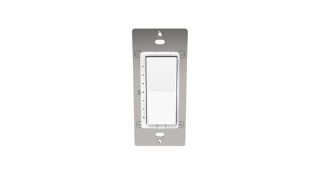
Product Image


3 - LED Light Mode
Sets bottom LED operation (in normal mode)Size: 1 byte
Default: 1
Minimum: 0
Maximum: 1
Possible values
| From | To | Desription |
|---|---|---|
| 0 | 1 | 0 = all LED ON if load is OFF 1 = all LED OFF if load is OFF |
4 - Invert Buttons
Sets paddle’s load orientationSize: 1 byte
Default: 0
Minimum: 0
Maximum: 1
Possible values
| From | To | Desription |
|---|---|---|
| 0 | 1 | 0 = Top of Paddle turns load ON 1 = Bottom of Paddle turns load ON |
5 - Sets the lowest dimming threshold
Possible values: 1-14 3-wire mode (1=16%, 14=25%) 2-wire mode (1=25%, 14=30%)Size: 1 byte
Default: 1
Minimum: 1
Maximum: 14
Possible values
| From | To | Desription |
|---|---|---|
| 1 | 14 | Possible values: 1-14 3-wire mode (1=16%, 14=25%) 2-wire mode (1=25%, 14=30%) |
6 - Enables/Disables Central Scene and multiple tap functions
0 = Central Scene Enabled, controls load with delay. Enables Multi-tap and press and hold 1 = Central Scene Disabled, controls load instantly. Disables multi-tap, central scene, press and holdSize: 1 byte
Default: 0
Minimum: 0
Maximum: 1
Possible values
| From | To | Desription |
|---|---|---|
| 0 | 1 | 0 = Central Scene Enabled, controls load with delay. Enables Multi-tap and press and hold 1 = Central Scene Disabled, controls load instantly. Disables multi-tap, central scene, press and hold |
11 - Set dimmer Ramp rate for remote control
Possible values: 0-90 0=No delay (instant ON), 1=1 secondSize: 1 byte
Default: 3
Minimum: 0
Maximum: 90
Possible values
| From | To | Desription |
|---|---|---|
| 0 | 90 | Possible values: 0-90 0=No delay (instant ON), 1=1 second |
12 - Set dimmer Ramp rate for local control
Possible values: 0-90 0=No delay (instant ON), 1=1 secondSize: 1 byte
Default: 3
Minimum: 0
Maximum: 90
Possible values
| From | To | Desription |
|---|---|---|
| 0 | 90 | Possible values: 0-90 0=No delay (instant ON), 1=1 second |
13 - Sets the display mode of the LEDs
0=Normal mode (LEDs show load status) 1=Status mode (custom LED status)Size: 1 byte
Default: 0
Minimum: 0
Maximum: 1
Possible values
| From | To | Desription |
|---|---|---|
| 0 | 1 | 0=Normal mode (LEDs show load status) 1=Status mode (custom LED status) |
14 - Sets the Normal display mode LED color
Possible values: 0-6 0=White, 1=Red, 2=Green, 3=Blue, 4=Magenta, 5=Yellow, 6=CyanSize: 1 byte
Default: 0
Minimum: 0
Maximum: 6
Possible values
| From | To | Desription |
|---|---|---|
| 0 | 6 | Possible values: 0-6 0=White, 1=Red, 2=Green, 3=Blue, 4=Magenta, 5=Yellow, 6=Cyan |
21 - Sets the Status mode LED 1 (bottom) color
Possible values: 0-7 0=Off, 1=Red, 2=Green, 3=Blue, 4=Magenta, 5=Yellow, 6=Cyan, 7=WhiteSize: 1 byte
Default: 0
Minimum: 0
Maximum: 7
Possible values
| From | To | Desription |
|---|---|---|
| 0 | 7 | Possible values: 0-7 0=Off, 1=Red, 2=Green, 3=Blue, 4=Magenta, 5=Yellow, 6=Cyan, 7=White |
22 - Sets the Status mode LED 2 color
Possible values: 0-7 0=Off, 1=Red, 2=Green, 3=Blue, 4=Magenta, 5=Yellow, 6=Cyan, 7=WhiteSize: 1 byte
Default: 0
Minimum: 0
Maximum: 7
Possible values
| From | To | Desription |
|---|---|---|
| 0 | 7 | Possible values: 0-7 0=Off, 1=Red, 2=Green, 3=Blue, 4=Magenta, 5=Yellow, 6=Cyan, 7=White |
23 - Sets the Status mode LED 3 color
Possible values: 0-7 0=Off, 1=Red, 2=Green, 3=Blue, 4=Magenta, 5=Yellow, 6=Cyan, 7=WhiteSize: 1 byte
Default: 0
Minimum: 0
Maximum: 7
Possible values
| From | To | Desription |
|---|---|---|
| 0 | 7 | Possible values: 0-7 0=Off, 1=Red, 2=Green, 3=Blue, 4=Magenta, 5=Yellow, 6=Cyan, 7=White |
24 - Sets the Status mode LED 4 color
Possible values: 0-7 0=Off, 1=Red, 2=Green, 3=Blue, 4=Magenta, 5=Yellow, 6=Cyan, 7=WhiteSize: 1 byte
Default: 0
Minimum: 0
Maximum: 7
Possible values
| From | To | Desription |
|---|---|---|
| 0 | 7 | Possible values: 0-7 0=Off, 1=Red, 2=Green, 3=Blue, 4=Magenta, 5=Yellow, 6=Cyan, 7=White |
25 - Sets the Status mode LED 5 color
Possible values: 0-7 0=Off, 1=Red, 2=Green, 3=Blue, 4=Magenta, 5=Yellow, 6=Cyan, 7=WhiteSize: 1 byte
Default: 0
Minimum: 0
Maximum: 7
Possible values
| From | To | Desription |
|---|---|---|
| 0 | 7 | Possible values: 0-7 0=Off, 1=Red, 2=Green, 3=Blue, 4=Magenta, 5=Yellow, 6=Cyan, 7=White |
26 - Sets the Status mode LED 6 color
Possible values: 0-7 0=Off, 1=Red, 2=Green, 3=Blue, 4=Magenta, 5=Yellow, 6=Cyan, 7=WhiteSize: 1 byte
Default: 0
Minimum: 0
Maximum: 7
Possible values
| From | To | Desription |
|---|---|---|
| 0 | 7 | Possible values: 0-7 0=Off, 1=Red, 2=Green, 3=Blue, 4=Magenta, 5=Yellow, 6=Cyan, 7=White |
27 - Sets the Status mode LED 7 (top) color
Possible values: 0-7 0=Off, 1=Red, 2=Green, 3=Blue, 4=Magenta, 5=Yellow, 6=Cyan, 7=WhiteSize: 1 byte
Default: 0
Minimum: 0
Maximum: 7
Possible values
| From | To | Desription |
|---|---|---|
| 0 | 7 | Possible values: 0-7 0=Off, 1=Red, 2=Green, 3=Blue, 4=Magenta, 5=Yellow, 6=Cyan, 7=White |
30 - LED Blink Frequency
Sets the dimmer Blink frequency for All LEDs in Status mode Possible values: 0, 1-255 0=No blink, 1=100ms ON then 100ms OFFSize: 1 byte
Default: 5
Minimum: 0
Maximum: 255
Possible values
| From | To | Desription |
|---|---|---|
| 0 | 255 | Possible values: 0, 1-255 0=No blink, 1=100ms ON then 100ms OFF |
31 - Enable LED Blink
Sets LED(s) 1-7 to Blink in Status mode Bitmask defines specific LEDs to enable for blinking: Note: this decimal value is derived from a hex code calculation based on the following: Bit 0 = led 1, Bit 1 = led 2, Bit 2 = led 3, Bit 3 = led 4, Bit 4 = led 5, Bit 5 = led 6, Bit 6 = led 7 IE: value of 1 = first LED, 64 = led 7Size: 1 byte
Default: 0
Minimum: 0
Maximum: 127
Possible values
| From | To | Desription |
|---|---|---|
| 0 | 127 | Bitmask defines specific LEDs to enable for blinking: Note: this decimal value is derived from a hex code calculation based on the following: Bit 0 = led 1, Bit 1 = led 2, Bit 2 = led 3, Bit 3 = led 4, Bit 4 = led 5, Bit 5 = led 6, Bit 6 = led 7 IE: value of 1 = first LED, 64 = led 7 |
32 - No Neutral Mode
Sets the Wire mode / no neutral mod of the switch 0 = 3 wire mode (Neutral, Line, & Load) 1 = 2 wire mode (Line & Load)Size: 1 byte
Default: 0
Minimum: 0
Maximum: 1
Possible values
| From | To | Desription |
|---|---|---|
| 0 | 1 | 0 = 3 wire mode (Neutral, Line, & Load) 1 = 2 wire mode (Line & Load) |
Follow this 2-step procedure to add (or remove) your new HomeSeer switch to (or from) your Z-Wave network: 1. Put your Z-Wave controller into inclusion (or exclusion) mode. Consult your controller’s manual if you’re unsure how to do this. 2. In rapid succession, tap the bottom paddle 2 times, then press & hold the bottom paddle for 3 seconds (tap-tap-press & hold). This will initiate the inclusion (or exclusion) process. Note: The switch will default to dimmer mode after Z-Wave exclusion
Follow this 2-step procedure to add (or remove) your new HomeSeer switch to (or from) your Z-Wave network: 1. Put your Z-Wave controller into inclusion (or exclusion) mode. Consult your controller’s manual if you’re unsure how to do this. 2. In rapid succession, tap the bottom paddle 2 times, then press & hold the bottom paddle for 3 seconds (tap-tap-press & hold). This will initiate the inclusion (or exclusion) process. Note: The switch will default to dimmer mode after Z-Wave exclusion
To be used only in the event that the network primary controller is lost or otherwise inoperable. 1. In rapid succession, tap the top paddle 3 times, then tap the bottom paddle 3 times. If all LEDs flash white 5 times, factory reset was successful. If not, repeat this procedure. Note: As this must be done very quickly, we recommend using 2 fingers for this operation; one on each paddle! Note: The switch will default to 3-wire mode and dimmer mode after factory reset.
Changing Wire Mode HS-WX300 may be installed with a neutral wire (3-wire mode) or without a neutral wire (2-wire mode). Selecting the correct wire mode will yield the best results, especially if the switch is configured as a dimmer. By default, 3-wire mode is enabled. To change the wire mode (at the switch): 1. Turn the power off 2. In rapid succession, tap the top paddle 2 times, then press & hold the top paddle for 3 seconds (tap-tap-press & hold) 3. Observe the behavior of the LEDs - If the bottom 3 LEDs flash white 3 times, HS-WX300 is configured for 3-wire mode - If the bottom 2 LEDs flash white 2 times, HS-WX300 is configured for 2-wire mode Note: Wire mode may also be changed by the hub using Z-Wave parameter 32. See the Z-Wave Parameters section at the end of this user guide.
*QR Code is located on the HS-WX300 metal yoke under the switch paddle.
Changing Switch Mode (Must be done BEFORE Z-Wave inclusion) HS-WX300 may be configured to operate as an ON-OFF switch or as a DIMMER. By default, it will operate as a dimmer. To change the switch mode, follow these steps: 1. Press & hold the small button located on the metal yoke next to the column of LEDs, OR if the trim plate is already installed, in rapid succession, tap the top paddle 3 times, then press & hold the top paddle for 3 seconds (tap-tap-tap-press & hold) 2. Observe the behavior of the LEDs - If all LEDs blink green 3 times, HS-WX300 is configured to function as a dimmer - If the bottom LED blinks blue 3 times, HS-WX300 is configured to function as an on-off switch
Note: The switch will default to 3-wire mode and dimmer mode after factory reset.
| Type | Value(s) |
|---|
| Sensor type |
|---|
| Illuminance |