QUBINO
Mini Dimmer
ZMNHHD1
Light Dimmer Switch
HW: 2 FW: 30.10:30.10
ZM5101
6.82.01
0x0159 (345)
0x0001 (1)
0x0055 (85)
ZC10-21077044
2021-07-08 10:40:58.992043
N/A
Enhanced 232 Slave
Always On Slave
The Qubino Mini Dimmer is the world most compact dimmer. MOSFET-switching light device that also supports control of low-voltage halogen lamps with electronic transformers, dimmable compact fluorescent lights, and dimmable LED bulbs. It can work with or without the neutral line (3 or 2-Wired system).
Mini Dimmer is a MOSFET-switching light device that also supports control of low-voltage halogen lamps with electronic transformers, dimmable compact fluorescent lights, and dimmable LED bulbs. It measures power consumption of the connected device. It supports push-button/momentary switches (default) and toggle switches. It can work with or without the neutral line. Qubino Mini Dimmer allows the easiest and quickest installation. It is designed to be mounted inside a “flush mounting box”, hidden behind a traditional wall switch. It acts as repeater in order to improve range and stability of Z-Wave™ network.
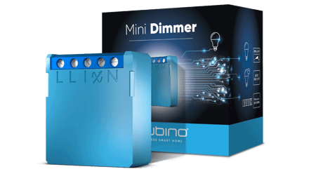
Product Image


1 - In-wall Switch Type for Load to control I1
With this parameter, you can select between push-button (momentary) and on/off toggle switch types.Size: 1 byte
Default: 0
Minimum: 0
Maximum: 1
Possible values
| From | To | Desription |
|---|---|---|
| 0 | 0 | push-button (momentary) |
| 1 | 1 | on/off toggle switch |
6 - Load type
With this parameter, you select the load type, dimmable or non dimmable. Device operating in dimmable mode on non dimmable load can lead to device or load malfunction. For non dimmable loads par. 6 must be set to 1. ⓘ NOTE: When par.6 set to 1 (non dimmable load) values of listed parameters will be ingnored (par.60 min. dimming value, par.61 max. dimming value, par.65 Dimm. Time when key presed par.66 dimm. Time when key hold, par.21 Double click function ⓘ NOTE: If the bulb is dimmable or non dimmable (generally valid for LED) is shown on the bulb itself or on packaging. ⓘ NOTE: Parameter 6 is replacing parameter 5. Present in previous version.Size: 1 byte
Default: 0
Minimum: 0
Maximum: 1
Possible values
| From | To | Desription |
|---|---|---|
| 0 | 0 | Dimmable load |
| 1 | 1 | Non dimmable load |
11 - Turn Load 1 Off Automatically with Timer
If Load is ON, you can schedule it to turn OFF automatically after a period of time defined in this parameter. The timer is reset to zero each time the device receives an ON or OFF command, either remotely (from the gateway (hub) or associated device) or locally from the switch.Size: 2 bytes
Default: 0
Minimum: 0
Maximum: 32536
Possible values
| From | To | Desription |
|---|---|---|
| 0 | 0 | Auto OFF Disabled |
| 1 | 32536 | 1 - 32536 seconds - Auto OFF timer enabled for a given amount of seconds |
12 - Turn Load 1 On Automatically with Timer
If Load is OFF, you can schedule it to turn ON automatically after a period of time defined in this parameter. The timer is reset to zero each time the device receives an OFF or ON command, either remotely (from the gateway (hub) or associated device) or locally from the switch.Size: 2 bytes
Default: 0
Minimum: 0
Maximum: 32536
Possible values
| From | To | Desription |
|---|---|---|
| 0 | 0 | Auto ON Disabled |
| 1 | 32536 | 1 - 32536 seconds - Auto ON timer enabled for a given amount of seconds |
21 - Enable/Disable the Double click function
If the Double click function is enabled, a fast double click on the push-button will set the dimming level to the maximum dimming value.Size: 1 byte
Default: 0
Minimum: 0
Maximum: 1
Possible values
| From | To | Desription |
|---|---|---|
| 0 | 0 | double click disabled |
| 1 | 1 | double click enabled |
30 - Restore on/off status for load after power failure
This parameter determines if on/off status is saved and restored for the load after power failure.Size: 1 byte
Default: 0
Minimum: 0
Maximum: 1
Possible values
| From | To | Desription |
|---|---|---|
| 0 | 0 | Device saves last on/off status and restores it after a power failure. |
| 1 | 1 | Device does not save on/off status and does not restore it after a power failure, it remains off. |
40 - Watt Power Consumption Reporting Threshold for Load
Choose by how much the power consumption needs to increase or decrease to be reported. Values correspond to percentages so if 10 is set (by default), the device will report any power consumption changes of 10% or more compared to the last reading. ⓘ NOTE: The power consumption needs to increase or decrease by at least 2 Watts to be reported, regardless of percentage set in this parameter.Size: 1 byte
Default: 10
Minimum: 0
Maximum: 100
Possible values
| From | To | Desription |
|---|---|---|
| 0 | 0 | Power consumption reporting disabled |
| 1 | 100 | 1% - 100% Power consumption reporting enabled. New value is reported only when Wattage in real time changes by more than the percentage value set in this parameter compared to the previous Wattage reading, starting at 1% (the lowest value possible). |
42 - Watt Power Consumption Reporting Time Threshold for Load
Set value refers to the time interval with which power consumption in Watts is reported (0 – 32767 seconds). If 300 is entered, energy consumption reports will be sent to the gateway (hub) every 300 seconds (or 5 minutes) if there was a change compared from the last report. ⓘNOTE: Values from 1 to 29 are ignored by device due to standard recommendation. ⓘNOTE: The report will be send only if there was a change compared to the last report.Size: 2 bytes
Default: 0
Minimum: 0
Maximum: 32767
Possible values
| From | To | Desription |
|---|---|---|
| 0 | 0 | Power consumption reporting on time interval disabled |
| 30 | 32767 | 30 - 32767seconds. Power consumption reporting enabled. Report is sent according to time interval (value) set here. |
60 - Minimum dimming value
The value set in this parameter determines the minimum dimming value (the lowest value which can be set on the device, when, for example, dimming lights with wall switch or slider in the GUI (Gateway - hub)) (Data type 1 byte dec) • default value 15 = 15% (minimum dimming value) • 0- 98 = 0% - 98%, step is 1%. Minimum dimming value is set by entering a value. ⓘ NOTE: The minimum level may not be higher than the maximum level!Size: 1 byte
Default: 15
Minimum: 0
Maximum: 98
Possible values
| From | To | Desription |
|---|---|---|
| 0 | 98 | 0% - 98%, step is 1%. Minimum dimming value is set by entering a value |
61 - Maximum dimming value
The value set in this parameter determines the maximum dimming value (the highest value which can be set on the device, when, for example, dimming lights with wall switch or slider in the GUI (Gateway - hub)) ⓘ NOTE: The maximum level may not be lower than the minimum level!Size: 1 byte
Default: 99
Minimum: 0
Maximum: 99
Possible values
| From | To | Desription |
|---|---|---|
| 1 | 99 | 2 % - 99 %, step is 1 %. Maximum dimming value is set by entering a value. |
65 - Dimming time when key pressed (soft on/off)
Choose the time during which the device will move between the min. and max. dimming values by a short press of the push-button I1.Size: 1 byte
Default: 1
Minimum: 1
Maximum: 127
Possible values
| From | To | Desription |
|---|---|---|
| 1 | 1 | 1 second |
| 1 | 127 | 1 seconds- 127 seconds, step is 1 second |
66 - Dimming time when key hold
Choose the time during which the Dimmer will move between the min. and max. dimming values during a continuous press of the push-button I1, by an associated device or through the UI controls (BasicSet, SwitchMultilevelSet).Size: 2 bytes
Default: 3
Minimum: 1
Maximum: 253
Possible values
| From | To | Desription |
|---|---|---|
| 1 | 127 | 1 second – 127 seconds |
| 128 | 253 | 1 minute – 126 minutes |
67 - Ignore start level
Choose whether the device should use (or disregard) the start dimming level value. If the device is configured to use the start level, it should start the dimming process from the currently set dimming level. This parameter is used with association group 3. NOTE: Parameter is valid only in Dimmer mode. In Switch mode the parameter has no effect.Size: 1 byte
Default: 0
Minimum: 0
Maximum: 1
Possible values
| From | To | Desription |
|---|---|---|
| 0 | 0 | use the start level value |
| 1 | 1 | ignore the start level value |
68 - Dimming duration
Choose the time during which the device will transition from the current value to the new target value. This parameter applies to the association group 3. NOTE: Parameter is valid only in Dimmer mode. In Switch mode the parameter has no effect.Size: 1 byte
Default: 0
Minimum: 0
Maximum: 127
Possible values
| From | To | Desription |
|---|---|---|
| 0 | 0 | dimming duration according to parameter 66 |
| 1 | 127 | from 1 to 127 seconds |
70 - Overload safety switch
The function allows for turning off the controlled device in case of exceeding the defined power for more than 5s. Controlled device can be turned back on by input I1 or sending a control frame. ⓘ NOTE: This functionality is not an overload safety protection, please check the technical specifications chapter for more details. In case of overload the following message will be send towards the controller: • COMMAND_CLASS_NOTIFICATION_V5 • The Alarm V1 type field set to 0x00 • Notification Type 0x08 and 0x08 (Overload detected)Size: 2 bytes
Default: 200
Minimum: 0
Maximum: 200
Possible values
| From | To | Desription |
|---|---|---|
| 0 | 0 | function not active |
| 1 | 200 | 1W - 200W |
71 - Calibration trigger
Choose when will be the calibration procedure triggered.Size: 1 byte
Default: 0
Minimum: 0
Maximum: 2
Possible values
| From | To | Desription |
|---|---|---|
| 1 | 1 | calibration done after power cycle regardless of inclusion status |
| 2 | 2 | force calibration. Calibration will start immediately |
72 - Calibration status (read only)
With this parameter you can check the calibration status.Size: 1 byte
Default: 2
Minimum: 1
Maximum: 2
Possible values
| From | To | Desription |
|---|---|---|
| 1 | 1 | calibration was successful |
| 2 | 2 | calibration failed |
73 - Alarm/Notification events
This parameter defines the module behaviour in case it receives any Alarm/Notification events. NOTE: When value 3 is selected the default time interval of the blinking is 10 minutes. It can be stopped with a button press or sending a control frame. To adjust the time interval please refer to parameter 74 – Alarm/Notification time interval.Size: 1 byte
Default: 0
Minimum: 0
Maximum: 3
Possible values
| From | To | Desription |
|---|---|---|
| 1 | 1 | turn OFF |
| 2 | 2 | turn ON |
| 3 | 3 | start blinking (output turns 1s ON, and 1s OFF) |
74 - Alarm/Notification time interval (dependant on parameter 73)
This parameter defines the time interval of the blinking state, once the module receives an alarm/notification event. Minimum step increase is 1 minute. NOTE: This parameter does not have any effect if parameter 73 is not set to value 3.Size: 1 byte
Default: 10
Minimum: 1
Maximum: 125
Possible values
| From | To | Desription |
|---|---|---|
| 1 | 125 | 1-125 minutes |
AUTOMATICALLY ADDING THE DEVICE TO A Z-WAVE NETWORK (SMARTSTART INCLUSION) 1. Scan QR code on device label and add S2 DSK to Provisioning List in gateway (hub) 2. Connect the device to the power supply 3. Inclusion will be initiated automatically within few seconds of connection to the power supply and the device will automatically enrol in your network (when the device is excluded and connected to the power supply it automatically enters the LEARN MODE state). NOTE: LEARN MODE state allows the device to receive network information from the controller. ⓘ SmartStart inclusion is a part of S2 security level, so if you want to use SmartStart, you need to include it as S2 Authenticated.
REMOVAL FROM A ZWAVE NETWORK (Z-WAVE EXCLUSION) 1. Connect the device to the power supply. 2. Make sure the device is within direct range of your Z-Wave gateway (hub) or use a hand-held Z-Wave remote to perform exclusion. 3. Enable add/remove mode on your Z-Wave gateway (hub). 4. Toggle the switch connected to the terminal I 3 times within 3 seconds (this procedure put the device in LEARN MODE). The device has to get On/Off signal 3 times, meaning 3 times push of the momentary switch or with toggle switch 3 times On and 3 times Off. OR Press and hold the S (Service) button between 2 and 6 seconds if connected power supply. For your safety use only 24-30 Vdc power supply when accessing to S (Service) button. This procedure put the device in LEARN MODE. 5. Exclusion with the switch connected to terminal I is not limited by time. 6. The device will be removed from your network, but any custom configuration parameters will not be erased. ⓘ NOTE: LEARN MODE state allows the device to receive network information from the controller.
12.5. Device factory reset 1. Connect the device to the power supply. 2. Within the first minute (60 seconds) the device is connected to the power supply, toggle the switch connected to the terminal I 5 times within 3 seconds. The device has to get On/Off signal 5 times, meaning 5 times push of the momentary switch or with toggle switch 5 times On and 5 times Off. OR Press and hold the S (Service) button for at least 6 seconds if connected to power supply. For your safety use only 24-30 Vdc power supply when accessing to S (Service) button. This procedure put the device in LEARN MODE. ⓘ NOTE: By resetting the device, all custom parameters previously set on the device will return to their default values, and the node ID will be deleted. Use this reset procedure only when the main gateway (hub) is missing or otherwise inoperable. If an end device is factory reset, it is reverted to the Z-Wave SmartStart inclusion state. ⓘ NOTE: the reset with switch connected to terminal I is possible only in the first minute after the device is connected to the power. ⓘ NOTE: after the reset is successfully done the autocalibration will trigger and the green LED will start blinking.
IMPORTANT: When adding the Mini Dimmer to a Z-Wave network with a controller supporting Security 2 (S2), the PIN code of the Z-Wave Device Specific Key (DSK) is required. The unique DSK code is printed on the product label and a copy is inserted in the packaging, which must not be lost. Do not remove the DSK from the product. As a backup measure, use the label in the packaging.
| Type | Value(s) |
|---|
| Group | Type |
|---|---|
| Power Management |
|
| Meter type |
|---|
| Electric Meter Consumption |