Philio
In Wall Roller shutter Controller
PAN34-HK
Window Covering DT
HW: 1 FW: 1.01
ZGM130
7.15.1
0x013C (316)
0x0001 (1)
0x0080 (128)
ZC12-21070275
2021-07-28 10:38:52.665139
N/A
Enhanced 232 Slave
Always On Slave
The in-wall Roller Shutter Controller is designed to switch rise/lower roller shutter connected to its terminals using radio waves, controllers and a push button directly connected to this Roller Controller.
The in-wall Roller Shutter Controller is designed to switch rise/lower roller shutter connected to its terminals using radio waves, controllers and a push button directly connected to this Roller Controller. This in-wall Roller Shutter Controller is a Z-Wave Plus TM enabled wireless device fully compatible with any Z-Wave TM enabled networks. This device is a security enabled Z-Wave Plus product that uses encrypted Z-Wave Plus messages to communicate to other security enabled Z-Wave Plus products. Z-Wave TM enabled devices displaying the Z-Wave TM logo can also be used with this device regardless of the manufacturer. This product can be operated in any Z-Wave network with other Z-Wave certified devices from other manufacturer. Within the network it will act as repeater regardless of vender to increase reliability of the network. Slim design let the Controller can easily hide itself into the wall box and that will be good for the house decoration. This device must be used in conjunction with a Security Enabled Z-Wave Controller in order to fully utilize all functions. Its functionality and supported command classes is identical when included as a secure and non-secure device. The new smart relay calibration technology can reduce the inrush current caused by the load and let the module work perfectly with many kind of Roller Shutter. This in-wall Roller Shutter Controller is able to detect position of the Shutter by using the patterned power measuring method, so it can be remote controlled not only fully up or down, but also can be adjusted to ex. 30% or 50%. And when manual controlled by push button, the controller also can memorize the position and send the new shutter position to its controller (ex. IP-Gateway).
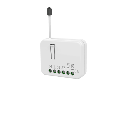
Product Image
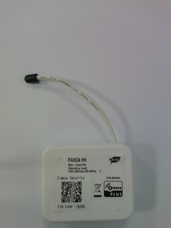
Front and side view
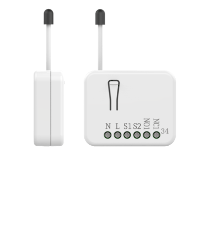
Front view


1 - Watt Meter Report Period
If the setting is configured for 1hour (set value =720), the PAN34 will report its instant power consumption every 1 hour to the node of Group 1. The maximum interval to report its instant power consumption is 45 hours (5s*32767/3600=45hr). Default value is 1 hour.Size: 2 bytes
Default: 720
Minimum: 0
Maximum: 32767
Possible values
| From | To | Desription |
|---|---|---|
| 0 | 0 | Disable auto Report |
| 1 | 32767 | 5s~45 hour |
2 - External switch mode
It is used to define the external button mode.Size: 1 byte
Default: 2
Minimum: 1
Maximum: 2
Possible values
| From | To | Desription |
|---|---|---|
| 1 | 0 | One Push button |
| 2 | 0 | Two Push button |
3 - Total moving time of curtain
This is a way for setting the total moving time of curtain manually.Size: 2 bytes
Default: 0
Minimum: 0
Maximum: 6000
Possible values
| From | To | Desription |
|---|---|---|
| 0 | 0 | The time depends on Moving Range Calibration |
| 1 | 6000 | 0.1s~600s |
4 - Watt threshold
The threshold is for PAN34 judging if the motor is running or not. The default value is 1 watts.Size: 1 byte
Default: 1
Minimum: 1
Maximum: 5
Possible values
| From | To | Desription |
|---|---|---|
| 1 | 5 | The threshold is a judgment for motor running or not |
5 - Watt differential
Whenever the watt value varies over 5%, PAN34 will send the meter report to group 1 nodes. The default value is 1 (5%).Size: 1 byte
Default: 1
Minimum: 0
Maximum: 1
Possible values
| From | To | Desription |
|---|---|---|
| 0 | 0 | It will not report Watt when change over 5% |
| 1 | 0 | It will report watt value when the di erential is over 5% |
6 - Timer offset for motor start running
This parameter is an offset to count for starting time of the motor. It will improve the inaccurate when moving to the middle position. The default value is 50.Size: 2 bytes
Default: 50
Minimum: 0
Maximum: 255
Possible values
| From | To | Desription |
|---|---|---|
| 0 | 255 | 0s ~ 2.55s, 50 = 0.5s |
1. Put your Z-Wave controller into inclusion mode by following the instructions provided by the controller manufacturer. 2. Pressing INCLUDE_BUTTON three times within 2 seconds will enter inclusion mode.
1. Put your Z-Wave controller into exclusion mode by following the instructions provided by the controller manufacturer. 2. Pressing INCLUDE_BUTTON three times within 2 seconds will enter exclusion mode. 3. Node ID has been excluded.
1. Pressing INCLUDE_BUTTON three times within 2 seconds will enter inclusion mode. 2. Within 1 second, press On/Off button again for 5 seconds. 3. IDs are excluded.
1. The product has a DSK string. Key in the first five digits to initiate the SmartStart process, or scan QR code. Ex: DSK: 18112-24021- 48001-62259-57092-27453-08187-47408 2. SmartStart enabled products can be added into a Z-Wave™ network by scanning the Z-Wave™ QR Code on the product, with a controller providing SmartStart inclusion. No further action is required and the SmartStart product will be added automatically to the closest network within 10 minutes of being switched on. Notice: The QR Code can be found on the device PAN34 or in the box.
| Type | Value(s) |
|---|
| Group | Type |
|---|---|
| Power Management |
|
| Meter type |
|---|
| Electric Meter Consumption |