Aeotec
illumino Wall Switch
ZWA038-A
Binary Switch
HW: 1 FW: 1.02
ZGM130
7.13.9
0x0371 (881)
0x0103 (259)
0x0026 (38)
ZC12-21080286
2021-08-05 09:46:58.321109
N/A
Enhanced 232 Slave
Always On Slave
Aeotec illumino Wall Switch is a Z-Wave™ Switch.
Aeotec illumino Wall Switch is a Z-Wave™ Switch specifically used to enable Z-Wave command and control (on/off) of any wall switches. In the event of power failure, non-volatile memory retains all programmed information relating to the unit’s operating status. It can connect to external manual switches to control the load ON/OFF independently. The illumino Wall Switch is also a security Z-Wave Plus™ device and supports Over The Air (OTA) feature for the products firmware upgrade.
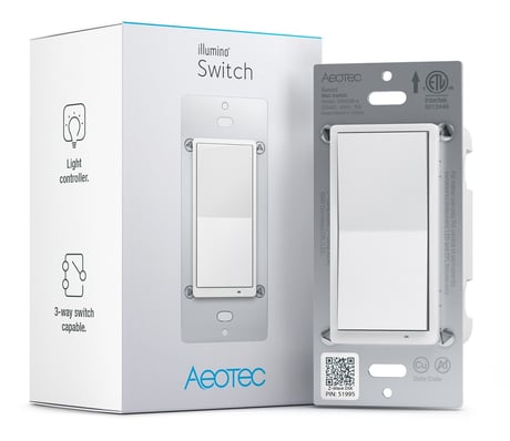
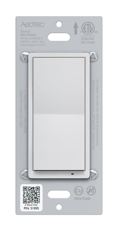
Product Image


20 - Power Restore
Status after power failure.Size: 1 byte
Default: 2
Minimum: 0
Maximum: 2
Possible values
| From | To | Desription |
|---|---|---|
| 0 | 0 | return to OFF |
| 1 | 1 | return to ON |
| 2 | 2 | returns to last known state when repowered |
40 - Auto Turn Off Timer
Timer that auto turn off once turned on.Size: 4 bytes
Default: 0
Minimum: 0
Maximum: 65535
Possible values
| From | To | Desription |
|---|---|---|
| 0 | 0 | Disable |
| 1 | 65535 | Auto turn off after 1s once turned on 65535 - Auto turn off after 65535s once turned on |
41 - Auto Turn On Timer
Timer that auto turn on once turned off.Size: 4 bytes
Default: 0
Minimum: 0
Maximum: 65535
Possible values
| From | To | Desription |
|---|---|---|
| 0 | 0 | Disable |
| 1 | 65535 | auto turn on after 1-65535s once turned off. |
80 - Instant Status Report
The command for status report.Size: 1 byte
Default: 2
Minimum: 0
Maximum: 2
Possible values
| From | To | Desription |
|---|---|---|
| 0 | 0 | Nothing |
| 1 | 1 | Basic Report |
| 2 | 2 | Binary Switch Report |
82 - Association Control Settings
Setting command for association group.Size: 1 byte
Default: 1
Minimum: 1
Maximum: 2
Possible values
| From | To | Desription |
|---|---|---|
| 1 | 1 | Basic Set |
| 2 | 2 | Binary Switch Set |
83 - Led Indicator Settings
Select the indicator function for output.Size: 1 byte
Default: 2
Minimum: 0
Maximum: 2
Possible values
| From | To | Desription |
|---|---|---|
| 0 | 0 | Disable |
| 1 | 1 | Momentary blink |
| 2 | 2 | LED follows status of output |
84 - Led Indicator Color For Output
Select the indicator color for output.Size: 1 byte
Default: 9
Minimum: 0
Maximum: 9
Possible values
| From | To | Desription |
|---|---|---|
| 0 | 0 | Disable |
| 1 | 1 | Red |
| 2 | 2 | Blue |
| 3 | 3 | Green |
| 4 | 4 | Pink |
| 5 | 5 | Cyan |
| 6 | 6 | Puple |
| 7 | 7 | Orange |
| 8 | 8 | Yellow |
| 9 | 9 | White |
85 - Led Indicator Color For Scene
Select the indicator color for scene.Size: 1 byte
Default: 2
Minimum: 0
Maximum: 9
Possible values
| From | To | Desription |
|---|---|---|
| 0 | 0 | Disable |
| 1 | 1 | Red |
| 2 | 2 | Blue |
| 3 | 3 | Green |
| 4 | 4 | Pink |
| 5 | 5 | Cyan |
| 6 | 6 | Purple |
| 7 | 7 | Orange |
| 8 | 8 | Yellow |
| 9 | 9 | White |
86 - Led Brightness
Setting the brightness of indicator.Size: 1 byte
Default: 60
Minimum: 0
Maximum: 100
Possible values
| From | To | Desription |
|---|---|---|
| 0 | 0 | Disable |
| 1 | 100 | 1%-100% level |
119 - External Switch Scene
Enable or disable the scene function of external(3-way) switch.Size: 1 byte
Default: 1
Minimum: 0
Maximum: 1
Possible values
| From | To | Desription |
|---|---|---|
| 0 | 0 | Disable |
| 1 | 1 | Enable |
120 - External Switch Type
Select the external(3-way) switch's type.Size: 1 byte
Default: 0
Minimum: 0
Maximum: 2
Possible values
| From | To | Desription |
|---|---|---|
| 0 | 0 | toggle on or off only |
| 1 | 1 | NO momentary switch |
| 2 | 2 | NC momentary switch |
121 - Output Control
Enable or disable output.Size: 1 byte
Default: 3
Minimum: 0
Maximum: 3
Possible values
| From | To | Desription |
|---|---|---|
| 0 | 0 | Disable |
| 1 | 1 | enable local control |
| 2 | 2 | enable central scene |
| 3 | 3 | enable local and central scene |
122 - Button Function
Select the paddle button functions.Size: 1 byte
Default: 0
Minimum: 0
Maximum: 2
Possible values
| From | To | Desription |
|---|---|---|
| 0 | 0 | up/ON, down/OFF |
| 1 | 1 | down/ON, up/OFF |
| 2 | 2 | toggle (up or down are the same) |
123 - Report Behavior
Select behavior for report and indicator when output is disable.Size: 1 byte
Default: 0
Minimum: 0
Maximum: 1
Possible values
| From | To | Desription |
|---|---|---|
| 0 | 0 | 0- report on/off status and change LED indicator when parameter 121 is set to 0 or 2 |
| 1 | 1 | 1- Don't report on/off status is pressed and parameter 121 is set to 0 or 2 |
1. Turn your primary controller into inclusion mode. 2. Press the Top/Buttom button once on product.
1. Turn your primary controller into exclusion mode. 2. 3*tap the Top/Buttom button on product.
Press and hold the Top/ Bottom button for 20s.
Page 2 and 9 in the User manual.
| Type | Value(s) |
|---|