Nice
Motion-Control
FGMS-001
Notification Sensor
HW: 1 FW: 3.04:03.04
ZM5202
6.51.07
0x010F (271)
0x0801 (2049)
0x1002 (4098)
ZC10-22037076
2022-03-30 10:07:58.354745
N/A
Enhanced 232 Slave
Reporting Sleeping Slave
Motion-Control is a universal Z-Wave™ multi-sensor. Along with detecting motion, the device measures the temperature and light intensity. The sensor has a built-in accelerometer to detect any tampering of the device.
Motion-Control is a universal Z-Wave™ multi-sensor. Along with detecting motion, the device measures the temperature and light intensity. The sensor has a built-in accelerometer to detect any tampering of the device. Motion-Control is a battery-powered device designed to be installed quickly and easily on any surface. The LED indicator signals motion, temperature level, operating mode and can indicate if the device is within the Z-Wave network. The device can be used for lighting scenes and presence monitoring systems.
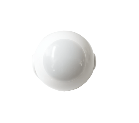
Product Image



1 - Motion detection - sensitivity
The lower the value, the more sensitive the PIR sensor is.Size: 2 bytes
Default: 15
Minimum: 8
Maximum: 255
Possible values
| From | To | Desription |
|---|---|---|
| 8 | 255 | Motion detection - sensitivity |
2 - Motion detection - blind time
PIR sensor is “blind” (insensitive) to motion after last detection for the amount of time specified in this parameter. Shorter time periods allow to detect motion more frequently, but the battery will be drained faster. Blind time should be shorter that the time period set in parameter 6 (alarm cancellation delay).Size: 1 byte
Default: 15
Minimum: 0
Maximum: 15
Possible values
| From | To | Desription |
|---|---|---|
| 0 | 15 | Motion detection - blind time |
3 - Motion detection - pulse counter
This parameter determines the number of moves required for the PIR sensor to report motion. The higher the value, the less sensitive the PIR sensor is. It is not recommended to modify this parameter settings!Size: 1 byte
Default: 1
Minimum: 0
Maximum: 3
Possible values
| From | To | Desription |
|---|---|---|
| 0 | 3 | Motion detection - pulse counter |
4 - Motion detection - window time
Period of time during which the number of moves set in parameter 3 must be detected in order for the PIR sensor to report motion. The higher the value, the more sensitive the PIR sensor is. It is not recommended to modify this parameter setting!Size: 1 byte
Default: 2
Minimum: 0
Maximum: 3
Possible values
| From | To | Desription |
|---|---|---|
| 0 | 3 | Motion detection - window time |
5 - Motion detection - alarm cancellation delay
Time period after which the motion alarm will be cancelled in the main controller and associated devices. Any motion detected during this period resets the timerSize: 2 bytes
Default: 30
Minimum: 1
Maximum: 32767
Possible values
| From | To | Desription |
|---|---|---|
| 1 | 32767 | alarm cancellation delay |
6 - Motion detection - operating mode
This parameter determines in which part of day the PIR sensor will be active. This parameter influences only the motion reports and associations. Tamper, light intensity and temperature measurements will be still active, regardless of this parameter settSize: 1 byte
Default: 0
Minimum: 0
Maximum: 2
Possible values
| From | To | Desription |
|---|---|---|
| 0 | 2 | operating mode |
7 - Motion detection - night/day
This parameter defines the difference between night and day in terms of light intensity, used in parameter 8.Size: 2 bytes
Default: 200
Minimum: 1
Maximum: 32767
Possible values
| From | To | Desription |
|---|---|---|
| 1 | 32767 | Motion detection - night/day |
8 - BASIC command class configuration
This parameter determines the command frames sent to 2nd association group (assigned to PIR sensor). Values of BASIC ON and BASIC OFF command frames can be modified with dedicated parameters (14 and 16).Size: 1 byte
Default: 0
Minimum: 0
Maximum: 2
Possible values
| From | To | Desription |
|---|---|---|
| 0 | 2 | BASIC command class configuration |
9 - BASIC ON command frame value
The command frame sent at the moment of motion detection. Further motion detections, during the cancellation time, will not result in sending the association.Size: 2 bytes
Default: 255
Minimum: 0
Maximum: 255
Possible values
| From | To | Desription |
|---|---|---|
| 0 | 255 | BASIC ON command frame value |
10 - BASIC OFF command frame value
The command frame sent at the moment of motion alarm cancellation, after cancellation delay time specified in parameter 6.Size: 2 bytes
Default: 0
Minimum: 0
Maximum: 255
Possible values
| From | To | Desription |
|---|---|---|
| 0 | 255 | BASIC OFF command frame value |
11 - Associations in Z-Wave network Security Mode
This parameter defines how commands are sent in specified association groups: as secure or non-secure. Parameter is active only in Z-Wave network security mode. It does not apply to 1st group “Lifeline"Size: 1 byte
Default: 0
Minimum: 0
Maximum: 8
Possible values
| From | To | Desription |
|---|---|---|
| 0 | 8 | Associations in Z-Wave network Security Mode |
12 - Tamper - sensitivity
This parameter determines the change in force acting on the device, that will result in reporting tamper alarm - gforce acceleration.Size: 1 byte
Default: 20
Minimum: 0
Maximum: 121
Possible values
| From | To | Desription |
|---|---|---|
| 0 | 121 | Tamper - sensitivity |
13 - Tamper - alarm cancellation delay
Time period after which a tamper alarm will be cancelled in the main controller and associated devices. Any tampering detected during this period will not extend the delay.Size: 2 bytes
Default: 30
Minimum: 1
Maximum: 32767
Possible values
| From | To | Desription |
|---|---|---|
| 1 | 32767 | Tamper - alarm cancellation delay |
14 - Tamper - operating modes
This parameter determines function of the tamper and sent reports. It is an advanced feature serving much more functions than just detection of tampering.Size: 1 byte
Default: 0
Minimum: 0
Maximum: 2
Possible values
| From | To | Desription |
|---|---|---|
| 0 | 2 | Tamper - operating modes |
15 - Tamper - alarm cancellation
This parameter allows to disable cancellation of the tamper alarm.Size: 1 byte
Default: 0
Minimum: 0
Maximum: 1
Possible values
| From | To | Desription |
|---|---|---|
| 0 | 1 | Tamper - alarm cancellation |
16 - Tamper - broadcast mode
The parameter determines whether the tamper alarm frame will or will not be sent in broadcast mode. Alarm frames sent in broadcast mode can be received by all of the devices within range (if they accept such frames), but not repeated by them.Size: 1 byte
Default: 0
Minimum: 0
Maximum: 1
Possible values
| From | To | Desription |
|---|---|---|
| 0 | 1 | Tamper - broadcast mode |
17 - Tamper - backward compatible broadcast mode
The parameter determines whether the backward compatible tamper alarm frame will or will not be sent in broadcast mode. Alarm frames sent in broadcast mode can be received by all of the devices within range (if they accept such frames), but not repeated by them. This parameter provides backward compatibility with controllers not supporting Z-Wave Plus.Size: 1 byte
Default: 0
Minimum: 0
Maximum: 1
Possible values
| From | To | Desription |
|---|---|---|
| 0 | 1 | Tamper - backward compatible broadcast mode |
18 - Illuminance report - threshold
This parameter determines the change in light intensity level resulting in illuminance report being sent to the main controller.Size: 2 bytes
Default: 200
Minimum: 0
Maximum: 32767
Possible values
| From | To | Desription |
|---|---|---|
| 0 | 32767 | Illuminance report - threshold |
19 - Illuminance report - interval
Time interval between consecutive illuminance reports. The reports are sent even if there is no change in the light intensity. Frequent illuminance reports will shorten the battery life. Parameter value under 5 may result in blocking the temperature reports.Size: 2 bytes
Default: 3600
Minimum: 0
Maximum: 32767
Possible values
| From | To | Desription |
|---|---|---|
| 0 | 32767 | Illuminance report - interval |
20 - Temperature report - threshold
This parameter determines the change in measured temperature that will result in new temperature report being sent to the main controller.Size: 2 bytes
Default: 10
Minimum: 0
Maximum: 255
Possible values
| From | To | Desription |
|---|---|---|
| 0 | 255 | Temperature report - threshold |
21 - Temperature measuring - interval
Time interval between consecutive temperature measurements. The shorter the time, the more frequently the temperature will be measured, but the battery life will shorten. Temperature measurements are still performed during the wake up, even if the periodic measuring is disabled (parameter 62 set to 0).Size: 2 bytes
Default: 900
Minimum: 0
Maximum: 32767
Possible values
| From | To | Desription |
|---|---|---|
| 0 | 32767 | Temperature measuring - interval |
22 - Temperature report - interval
Time interval between consecutive temperature reports. The reports are sent even if there is no change in the temperature. Frequent temperature reports will shorten the battery life. Parameter value under 5 may result in blocking the illuminance reports.Size: 2 bytes
Default: 0
Minimum: 0
Maximum: 32767
Possible values
| From | To | Desription |
|---|---|---|
| 0 | 32767 | Temperature report - interval |
23 - Temperature offset
The value to be added to the actual temperature, measured by the sensor (temperature compensation).Size: 2 bytes
Default: 0
Minimum: -1000
Maximum: 1000
Possible values
| From | To | Desription |
|---|---|---|
| -1000 | 1000 | Temperature offset |
24 - Visual LED indicator - signalling mode
This parameter determines the way in which visual indicator behaves after motion has been detected. Flashlight Mode - visual indicator glows in white for 10 seconds. If value of parameter 80 is set to 11, each detected motion extends the glowing by next 10 seconds.Size: 1 byte
Default: 10
Minimum: 0
Maximum: 24
Possible values
| From | To | Desription |
|---|---|---|
| 0 | 24 | Visual LED indicator - signalling mode |
25 - Visual LED indicator - brightness
This parameter determines the brightness of the visual LED indicator when indicating motion.Size: 1 byte
Default: 50
Minimum: 0
Maximum: 100
Possible values
| From | To | Desription |
|---|---|---|
| 0 | 100 | Visual LED indicator - brightness |
26 - Visual LED indicator - illuminance for low indicator brightness
Light intensity level below which brightness of visual indicator is set to 1%. The value of parameter 83 must be higher than the value of parameter 82.Size: 2 bytes
Default: 83
Minimum: 0
Maximum: 83
Possible values
| From | To | Desription |
|---|---|---|
| 0 | 83 | Visual LED indicator - illuminance for low indicator brightness |
27 - Visual LED indicator - illuminance for high indicator brightness
Light intensity level above which brightness of visual indicator is set to 100%Size: 2 bytes
Default: 1000
Minimum: 82
Maximum: 32767
Possible values
| From | To | Desription |
|---|---|---|
| 82 | 32767 | Visual LED indicator - illuminance for high indicator brightness |
28 - Visual LED indicator - temperature for blue colour
This parameter determines minimal temperature that will result in blue visual indicator colour. Relevant only when parameter 80 has been properly configured.Size: 2 bytes
Default: 0
Minimum: 0
Maximum: 87
Possible values
| From | To | Desription |
|---|---|---|
| 0 | 87 | Visual LED indicator - temperature for blue colour |
29 - Visual LED indicator - temperature for red colour
This parameter determines minimal temperature that will result in red visual indicator colour. Relevant only when parameter 80 has been properly configured.Size: 2 bytes
Default: 86
Minimum: 86
Maximum: 255
Possible values
| From | To | Desription |
|---|---|---|
| 86 | 255 | Visual LED indicator - temperature for red colour |
30 - Visual LED indicator - tamper alarm
This parameter allows to enable/disable indicating tamper alarm (flashing white, red and blue).Size: 1 byte
Default: 1
Minimum: 0
Maximum: 1
Possible values
| From | To | Desription |
|---|---|---|
| 0 | 1 | Visual LED indicator - tamper alarm |
To add the device to the Z-Wave network manually: 1. Open the cover. 2. Place the Motion-Control within the direct range of your Z-Wave controller. 3. Set the main controller in (security/non-security) add mode (see the controller’s manual). 4. Quickly, three times press the B-button. 5. Wait for the adding process to end. 6. Successful adding will be confirmed by the Z-Wave controller’s message
1. Open the cover. 2. Place the Motion-Control within the direct range of your Z-Wave controller. 3. Set the main controller in remove mode (see the controller’s manual). 4. Quickly, three times press the B-button. 5. Wait for the removing process to end. 6. Successful removing will be confirmed by the Z-Wave controller’s message.
1x click: wake up the device or select the desired menu option (if menu is active)
Resetting the Motion-Control Reset procedure erases the memory, including all information on the Z-Wave network and the main controller. 1. Open the cover. 2. Press and hold the B-button. 3. Wait for visual indicator to glow yellow (2nd menu position). 4. Release the B-button. 5. Click the B-button to confirm selection. 6. After few seconds the device will be reset, which is signalled with the red, fading visual indicator colour.
| Group | Type |
|---|---|
| Home Security |
|
| Sensor type |
|---|
| Air Temperature |
| Motion Direction |