Cherubini
META ENERGY DRIVEN SWITCH-C 7
A510086
Meter Sensor DT
HW: 01 FW: 07.00
ZGM130S037HGN2 / ZGM130S037HGN1
7.16.3
0x0149 (329)
N/A
0x0004 (4)
ZC14-22050103
2022-05-05 07:46:15
N/A
Enhanced 232 Slave
Always On Slave
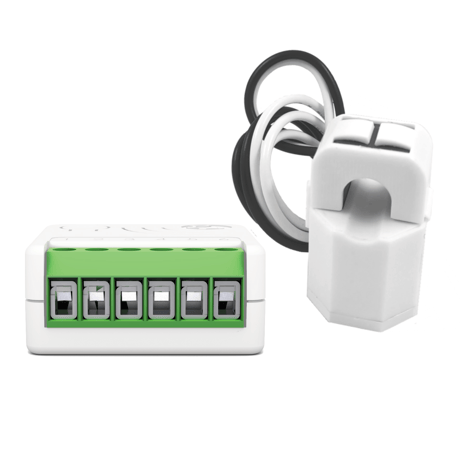
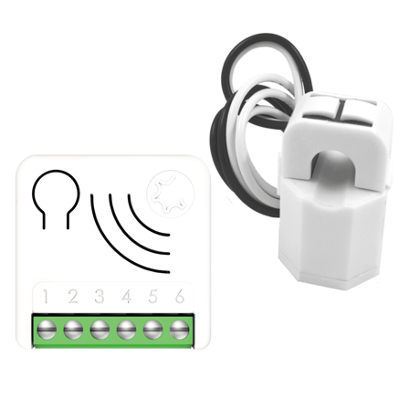
META Energy Driven Switch C 7 monitors all parameters, usage, faults and overloads of the electrical system. A bi-directional meter that measures consumed and produced power.


21 - OUT_TYPE
Define the output type.Size: 1 byte
Default: 0
Minimum: 0
Maximum: 1
Possible values
| From | To | Desription |
|---|---|---|
| 0 | 0 | Direct load or normally Open relay |
| 1 | 1 | Normally Closed relay |
23 - STARTUP_OUT
Define the output level on startup.Size: 1 byte
Default: 2
Minimum: 0
Maximum: 2
Possible values
| From | To | Desription |
|---|---|---|
| 0 | 0 | OFF |
| 1 | 1 | ON |
| 2 | 2 | Previous status |
31 - OFF TIMEOUT
Time in tenth of seconds after which the output will be switched Off.Size: 4 bytes
Default: 0
Minimum: 0
Maximum: 360000
Possible values
| From | To | Desription |
|---|---|---|
| 0 | 0 | Disabled |
| 0 | 360000 | Specific time expressed in tenth of seconds for Status change. |
32 - ON TIMEOUT
Time in tenth of second after which the output will be switched On.Size: 4 bytes
Default: 0
Minimum: 0
Maximum: 360000
Possible values
| From | To | Desription |
|---|---|---|
| 0 | 0 | Disabled |
| 0 | 360000 | Specific time expressed in tenth of seconds for Status change. |
40 - UP_POWER_LOCAL_CONTROL
The value used to control the integrated Relay in case of Up Power Event.Size: 1 byte
Default: 1
Minimum: 0
Maximum: 1
Possible values
| From | To | Desription |
|---|---|---|
| 0 | 0 | OFF |
| 1 | 1 | ON |
41 - DOWN_POWER_LOCAL_CONTROL
The value used to control the integrated Relay in case of Down Power Event.Size: 1 byte
Default: 1
Minimum: 0
Maximum: 1
Possible values
| From | To | Desription |
|---|---|---|
| 0 | 0 | OFF |
| 1 | 1 | ON |
42 - METER_TYPE
Defines how positive and negative power is treated.Size: 1 byte
Default: 3
Minimum: 0
Maximum: 4
Possible values
| From | To | Desription |
|---|---|---|
| 0 | 0 | As is (The meter is connected in a bidirectional system and you want to measure consumed and produced energy) |
| 1 | 1 | Negative value is considered 0 (The meter is connected in a bidirectional system, but you are interested only in consumed energy) |
| 2 | 2 | Positive value is considered 0 (The meter is connected in a bidirectional system, but you are interested only in produced energy) |
| 3 | 3 | All values are considered positive (The meter is connected in a system that only consumes Energy) |
| 4 | 4 | All values are considered negative (The meter is connected in a system that only produces Energy) |
43 - CT_TYPE
Define the Model of Current Transformer connected to the device.Size: 1 byte
Default: 1
Minimum: 1
Maximum: 2
Possible values
| From | To | Desription |
|---|---|---|
| 1 | 1 | Standard Type |
| 2 | 2 | Type 2 version |
44 - UP POWER_REMOTE_CONTROL
The value used to control Up Power Group.Size: 1 byte
Default: 0
Minimum: 0
Maximum: 100
Possible values
| From | To | Desription |
|---|---|---|
| 0 | 99 | Specific value (where 0 equals OFF) |
| 100 | 100 | ON |
45 - DOWN_POWER_REMOTE_CONTROL
The value used to control Down Power Group.Size: 1 byte
Default: 100
Minimum: 0
Maximum: 100
Possible values
| From | To | Desription |
|---|---|---|
| 0 | 99 | Specific value (where 0 equals OFF) |
| 100 | 100 | ON |
46 - OVER_VOLTAGE_LIMIT
The value used to control Up Power Group.Size: 2 bytes
Default: 2530
Minimum: 900
Maximum: 2530
Possible values
| From | To | Desription |
|---|---|---|
| 900 | 2530 | Over Voltage limit |
47 - DOWN_VOLTAGE_LIMIT
Define the Down Voltage Limit in tenth of volt.Size: 2 bytes
Default: 2070
Minimum: 900
Maximum: 2530
Possible values
| From | To | Desription |
|---|---|---|
| 900 | 2530 | Down Voltage limit |
50 - UP_POWER_LEVEL
Sets the level of Watts beyond which time of permanence above this level is calculated.Size: 4 bytes
Default: 0
Minimum: 0
Maximum: 100000
Possible values
| From | To | Desription |
|---|---|---|
| 0 | 0 | Up Power Event Disabled |
| 1 | 100000 | Instantaneous power in Watts |
51 - UP_POWER_TYPE
Defines if the Up Power is consumed or produced.Size: 1 byte
Default: 0
Minimum: 0
Maximum: 1
Possible values
| From | To | Desription |
|---|---|---|
| 0 | 0 | Consumed |
| 1 | 1 | Produced |
52 - UP_POWER_FIRST_TIMEOUT
Defines the time of permanence in seconds above the Up power level after which the First Up Power event occurs.Size: 2 bytes
Default: 30
Minimum: 2
Maximum: 7200
Possible values
| From | To | Desription |
|---|---|---|
| 2 | 7200 | Specific time expressed in seconds |
53 - UP_POWER_NEXT_TIMEOUT
Defines the time of permanence in seconds above the Up power level after which the Next Up Power event occurs.Size: 2 bytes
Default: 5
Minimum: 2
Maximum: 7200
Possible values
| From | To | Desription |
|---|---|---|
| 2 | 7200 | Specific time expressed in seconds |
54 - DOWN_POWER_LEVEL
Sets the level of Watts beyond which time of permanence below this level is calculated.Size: 4 bytes
Default: 0
Minimum: 0
Maximum: 100000
Possible values
| From | To | Desription |
|---|---|---|
| 0 | 0 | Down Power Event Disabled |
| 1 | 100000 | Instantaneous power in Watt |
55 - DOWN POWER TYPE
Defines if the Down Power is consumed or produced.Size: 1 byte
Default: 0
Minimum: 0
Maximum: 1
Possible values
| From | To | Desription |
|---|---|---|
| 0 | 0 | Consumed |
| 1 | 1 | Produced |
56 - DOWN_POWER_FIRST_TIMEOUT
Defines the time of permanence in seconds below the Down Power level after which the first Down Power event occurs.Size: 2 bytes
Default: 30
Minimum: 2
Maximum: 7200
Possible values
| From | To | Desription |
|---|---|---|
| 2 | 7200 | Specific time expressed in seconds |
57 - DOWN_POWER_NEXT_TIMEOUT
Defines the time of permanence in seconds below the Down Power level after which the next Up Down event occurs.Size: 2 bytes
Default: 5
Minimum: 2
Maximum: 7200
Possible values
| From | To | Desription |
|---|---|---|
| 2 | 7200 | Specific time expressed in seconds |
58 - PROTECTION_TIME
Define the minimum time is seconds, after which an Up/Down Power Event can be triggered again.Size: 2 bytes
Default: 60
Minimum: 2
Maximum: 3600
Possible values
| From | To | Desription |
|---|---|---|
| 2 | 3600 | Protection time in seconds |
71 - METER_REPORT_MAX_DELAY
The Maximum Time in minutes after which the next Meter sequence report will be sent.Size: 1 byte
Default: 10
Minimum: 1
Maximum: 120
Possible values
| From | To | Desription |
|---|---|---|
| 1 | 120 | The maximum delay in minutes from a sequence of meter report and the next |
75 - METER_ISTANT_REPORT
The percentage of Power change from the last sent report that triggers a new meter report sequence.Size: 1 byte
Default: 20
Minimum: 0
Maximum: 100
Possible values
| From | To | Desription |
|---|---|---|
| 0 | 0 | No report is sent (for any power change) |
| 1 | 100 | The percentage of Power change from the last sent report that triggers a new meter report sequence |
76 - REPORT_CONFIG
Define which Report scale will be sent.Size: 1 byte
Default: 117
Minimum: 0
Maximum: 117
Possible values
| From | To | Desription |
|---|---|---|
| 0 | 0 | None |
| 1 | 1 | Energy |
| 4 | 4 | Power |
| 16 | 16 | Voltage |
| 32 | 32 | Current |
| 64 | 64 | Power Factor |
All META Serie 7 devices are compatible with all Z-Wave/Z-Wave Plus certified controllers. The devices support both the Network Wide Inclusion mechanism (which offers the ability to be included in a network, even if the device is not directly connected to the controller) and Normal Inclusion. By default, the inclusion procedure starts in Normal Inclusion mode and after a short timeout the procedure continues in Network Wide Inclusion mode that lasts for about 20 Seconds. Only a controller can add the device into the network. After activating the inclusion function by the controller, the device can be added by setting it in Learn Mode. Before including the device, the LED status indicator is solid RED. The adding of a device is executed by activating the adding procedure in the inclusion section of the controller interface and executing 1 or 3 click on the integrated button (the device is set in Learn Mode). As soon as the inclusion procedure initiates the LED indicator starts a sequence of GREEN-BLUE blinks. The device is included in the network when the LED status is OFF and the interview is completed.
Only a controller can remove the device from the network. After activating the exclusion function by the controller, the device can be removed by setting it in Learn Mode. The procedure of exclusion can be activated by Removing a node from the Z-Wave network and executing 1 or 3 click on the integrated button; as soon as the exclusion initiates, the LED indicator starts a sequence of RED-BLUE blinks. The device is excluded from the network when the LED status indicator is solid RED and the App_status in the interface is OK.
The device can be reset to the original factory settings with 6 consecutive clicks on the integrated button. After the reset is completed, the device will reboot and a RED solid led is showed. INFO: If the reset is performed while the device is still part of a network, it notifies the other devices that it has been removed (Device Reset Locally Notification).
OTHER SPECIAL FEATURES Timer Management The device has a timer that can be configured to turn ON and/or OFF the local relay. The timer starts its counter after a relay commutation. Active Energy management Energy Driven Switch C 7 can implement an active energy saving policy by managing electric loads in order to maximize the self-consumption during the greater production period of a wind power or photovoltaic plant, optimizing the net metering and the energy saving. Refer to the configuration section for the parameter details. Overvoltage Protection The product can be configured to detect if the voltage remains within a range defined by the user, who can set an Overvoltage limit and a Down voltage limit. When the voltage values go out of the defined range, a notification is sent to the lifeline association group. Offline setup Mode The device has a unique feature that allows to configure some parameters without using any user interface. This feature enables the professional user to setup the main features of the device in the field even if the device is not included in a Z-Wave Network. When the device will be included in the network all these configuration parameters will be maintained.
Page 10 - S2 Secure inclusion- When adding META Serie 7 devices to a Z-Wave network with a controller supporting Security 2 Authenticated (S2), the PIN code of the Z-Wave Device Specific Key (DSK) is required.
| Group | Type |
|---|---|
| Power Management |
|