WiDom
Smart Roller Shutter 7
UMS700
Window Covering DT
HW: 01 FW: 02.01
ZGM130S037HGN2 / ZGM130S037HGN1
7.16.3
0x0149 (329)
N/A
0x0004 (4)
ZC14-22100151
2022-10-26 08:49:35
N/A
Enhanced 232 Slave
Always On Slave
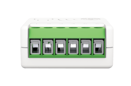
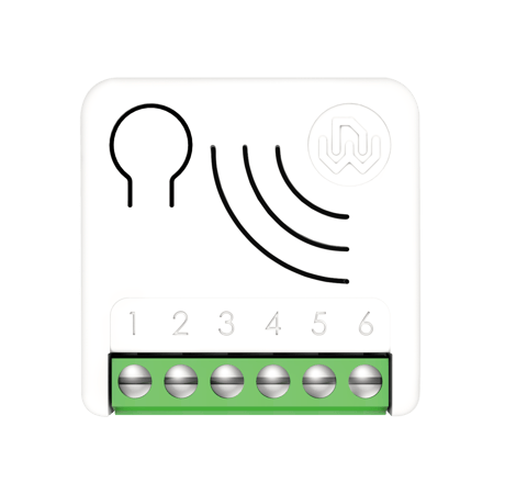
Smart Roller Shutter 7 is an "in wall device", for the multilevel control of roller shutter motors. It can accurately control the opening and closing of blinds, curtains, shutters, venetian blinds as requested by the user through local commands or remotely.


2 - ON_FAVORITE_LEVEL
The On level reached when the Up Button received a double click.Size: 1 byte
Default: 80
Minimum: 50
Maximum: 99
Possible values
| From | To | Desription |
|---|---|---|
| 50 | 99 | 50-99% opening level (99% correspond to completely open) |
3 - OFF_FAVORITE_LEVEL
The Off level reached when the Down Button received a double click.Size: 1 byte
Default: 20
Minimum: 0
Maximum: 49
Possible values
| From | To | Desription |
|---|---|---|
| 0 | 49 | 0-49% opening level (0 correspond to completely closed) |
20 - CALIBRATION_COMPLETE
Define if the device has been calibrated.Size: 1 byte
Default: 0
Minimum: 0
Maximum: 1
Possible values
| From | To | Desription |
|---|---|---|
| 0 | 0 | TO_BE_DONE (Calibration to be done) |
| 1 | 1 | DONE (Calibration has been done) |
21 - MAX_LEVEL_TIME
Time to reach Max level starting from the Min Level Defines the time in thousandth of a second necessary to reach the complete open position starting from complete close position.Size: 4 bytes
Default: 100
Minimum: 100
Maximum: 100000
Possible values
| From | To | Desription |
|---|---|---|
| 100 | 100000 | Time expressed in thousandths of a second |
22 - MIN_LEVEL_TIME
Time to reach Min level starting from the Max Level Defines the time thousandth of a second necessary to reach the complete close position starting from complete open position.Size: 4 bytes
Default: 100
Minimum: 100
Maximum: 100000
Possible values
| From | To | Desription |
|---|---|---|
| 100 | 100000 | Time expressed in thousandths of a second |
23 - INVERTION_TIMEOUT
Time in thousandth of a second after which the movement direction can be changed.Size: 4 bytes
Default: 500
Minimum: 500
Maximum: 3000
Possible values
| From | To | Desription |
|---|---|---|
| 500 | 3000 | Time expressed in thousandths of a second |
24 - LIMIT_SWITCH_TIMEOUT
Time in thousandth of a second for recognizing that the limit switch has been reached.Size: 4 bytes
Default: 2500
Minimum: 1000
Maximum: 5000
Possible values
| From | To | Desription |
|---|---|---|
| 1000 | 5000 | Time expressed in thousandths of a second |
25 - FINE_CALIBRATION
Adjustment in Percentage value of the 50% level position after the initial calibration. Increasing/decreasing of this value will move the 50% level in the UP direction/Down direction,Size: 1 byte
Default: 100
Minimum: 50
Maximum: 150
Possible values
| From | To | Desription |
|---|---|---|
| 50 | 150 | Expressed in percentage |
37 - REPORT_FREQUENCY
Time in seconds after which the new position report is sent if the target position is not reached. When the target position has been reached a final position report is sent.Size: 1 byte
Default: 5
Minimum: 1
Maximum: 100
Possible values
| From | To | Desription |
|---|---|---|
| 1 | 100 | Time expressed in second |
38 - SEND_MULTILEVEL_REPORT
Define if the Multilevel Report will be sent unsolicited. (0: report is not sent, 1: report is sent)Size: 1 byte
Default: 0
Minimum: 0
Maximum: 1
Possible values
| From | To | Desription |
|---|---|---|
| 0 | 0 | Report is not sent |
| 1 | 1 | Report is sent |
61 - INVERT_MOVEMENT
Movement inversion If after the calibration, the movement of the motor is opposite to the command issue (goes up, if it is required to go down and vice versa) the movement can be inverted. This parameter can be set also using the offline setup mode.Size: 1 byte
Default: 0
Minimum: 0
Maximum: 1
Possible values
| From | To | Desription |
|---|---|---|
| 0 | 0 | NOT_INVERTED |
| 1 | 1 | INVERTED |
Page 4 - All Smart Serie 7 devices are compatible with all Z-Wave™/Z-Wave Plus™ certified controllers. The devices support both the Network Wide Inclusion mechanism (which offers the ability to be included in a network, even if the device is not directly connected to the controller) and Normal Inclusion. By default, the inclusion procedure starts in Normal Inclusion mode and after a short timeout the procedure continues in Network Wide Inclusion mode that lasts for about 20 Seconds. Only a controller can add the device into the network. After activating the inclusion function by the controller, the device can be added by setting it in Learn Mode.
Page 5 -Only a controller can remove the device from the network. After activating the exclusion function by the controller, the device can be removed by setting it in Learn Mode. The procedure of exclusion can be activated by Removing a node from the Z-Wave™ network and executing 1 or 3 click on the integrated button; as soon as the exclusion initiates, the LED indicator starts a sequence of RED-BLUE blinks. The device is excluded from the network when the LED status indicator is solid RED and the App_status in the interface is OK.
The device can be reset to the original factory settings with 6 consecutive clicks on the integrated button. After the reset is completed, the device will reboot and a RED solid led is showed. Please use this procedure only when the network primary controller is missing or otherwise inoperable. INFO: If the reset is performed while the device is still part of a network, it notifies the other devices that it has been removed (Device Reset Locally Notification).
Offline setup Mode The device has a unique feature that allows to configure some parameters without using any user interface. This feature enables the professional user to setup the main features of the device in the field even if the device is not included in a Z-Wave™ Network. When the device will be included in the network all these configuration parameters will be maintained. Favorite positions The system can set two favorite positions: one for the upward movements (opening movements) Favorite level for ON position, the other for the downward movements (closing movements) Favorite level for OFF position. Calibration Defines the status of the calibration procedure. By default, the calibration starts in automatic mode as soon as a movement command has been set by external switch or by Z-Wave™ network.
page 5 - When adding Smart Serie 7 devices to a Z-Wave™ network with a controller supporting Security 2 Authenticated (S2), the PIN code of the Z-Wave™ Device Specific Key (DSK) is required. The unique DSK code is printed on the product label. The first five digits of the key are highlighted and underlined to help the user identify the PIN code.