Alarm.com
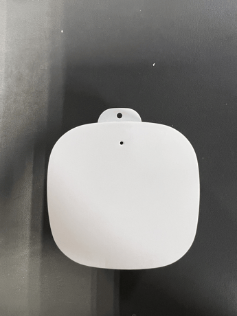
Smart Noise Monitor (Sigma Nu)
ADC-N10-N
Multilevel Sensor DT
HW: 01 FW: 00.49:00.51
ZGM130S037HGN2 / ZGM130S037HGN1
7.17.2
0x0094 (148)
N/A
0x0001 (1)
ZC14-22110168
2022-11-21 15:26:53
N/A
Enhanced 232 Slave
Always On Slave
Noise Monitor sensor that measures detected audio levels. Indoor Use Only.


1 - Loudness Data Reporting Period – Override
The time in seconds between Loudness data report when the override is enabled (parameter 0x05)Size: 2 bytes
Default: 180
Minimum: 0
Maximum: 5400
Possible values
| From | To | Desription |
|---|---|---|
| 0 | 5400 | seconds |
2 - Loudness Data Read Interval
The time in milliseconds between each read of loudness data from the microphoneSize: 2 bytes
Default: 1000
Minimum: 200
Maximum: 10000
Possible values
| From | To | Desription |
|---|---|---|
| 200 | 10000 | milliseconds |
3 - Loudness Data Aggregation Type
The algorithm used for aggregating loudness dataSize: 1 byte
Default: 4
Minimum: 1
Maximum: 4
Possible values
| From | To | Desription |
|---|---|---|
| 1 | 1 | Instantaneous reading |
| 2 | 2 | Average of all readings taken during the reporting period |
| 3 | 3 | Maximum of all readings taken during the reporting period |
| 4 | 4 | Sustained maximum (over Loudness Data Window seconds) |
4 - Loudness Data Sustain Window
The time period (seconds) used by “sustained" algorithms to group data.Size: 2 bytes
Default: 10
Minimum: 2
Maximum: 600
Possible values
| From | To | Desription |
|---|---|---|
| 2 | 600 | seconds |
5 - Override Loudness Data Reporting Period
Whether to override the automatic reporting period algorithm with the Universal Loudness Data Reporting Period.Size: 1 byte
Default: 0
Minimum: 0
Maximum: 1
Possible values
| From | To | Desription |
|---|---|---|
| 0 | 0 | Don't override |
| 1 | 1 | Override |
16 - Loudness Data Reporting Period – Low Noise Range
The time in seconds between Loudness data report, when in the Low Noise Range and the override is disabled.Size: 2 bytes
Default: 5400
Minimum: 180
Maximum: 5400
Possible values
| From | To | Desription |
|---|---|---|
| 180 | 5400 | seconds |
17 - Loudness Data Reporting Period – Medium Noise Range
The time in seconds between Loudness data report, when in the Medium Noise Range and the override is disabled.Size: 2 bytes
Default: 1800
Minimum: 180
Maximum: 5400
Possible values
| From | To | Desription |
|---|---|---|
| 180 | 5400 | seconds |
18 - Loudness Data Reporting Period – High Noise Range
The time in seconds between Loudness data report, when in the High Noise Range and the override is disabled.Size: 2 bytes
Default: 600
Minimum: 180
Maximum: 5400
Possible values
| From | To | Desription |
|---|---|---|
| 180 | 5400 | seconds |
19 - Loudness Data Reporting Period – Very High Noise Range
The time in seconds between Loudness data report, when in the Very High Noise Range and the override is disabled.Size: 2 bytes
Default: 180
Minimum: 180
Maximum: 5400
Possible values
| From | To | Desription |
|---|---|---|
| 180 | 5400 | seconds |
22 - Medium Noise Range
Width (dB) of the Medium Noise range.Size: 1 byte
Default: 10
Minimum: 0
Maximum: 45
Possible values
| From | To | Desription |
|---|---|---|
| 0 | 45 | dB |
23 - High Noise Range
Width (dB) of the High Noise range.Size: 1 byte
Default: 10
Minimum: 0
Maximum: 45
Possible values
| From | To | Desription |
|---|---|---|
| 0 | 45 | dB |
24 - Very High Noise Range
Width (dB) of the Very High Noise rangeSize: 1 byte
Default: 11
Minimum: 0
Maximum: 45
Possible values
| From | To | Desription |
|---|---|---|
| 0 | 45 | dB |
26 - Range Adjust Period
The duration of recent loudness readings to consider when determining current range This parameter only has an effect if the Range Adjust Aggregation Type (parameter 0x1B) is NOT set to Instantaneous (1)Size: 2 bytes
Default: 10
Minimum: 1
Maximum: 65535
Possible values
| From | To | Desription |
|---|---|---|
| 1 | 65535 | seconds |
27 - Range Adjust Aggregation Type
Which algorithm to use for determining current range.Size: 1 byte
Default: 4
Minimum: 1
Maximum: 4
Possible values
| From | To | Desription |
|---|---|---|
| 1 | 1 | Instantaneous reading |
| 2 | 2 | Average of all readings taken during the reporting period |
| 3 | 3 | Maximum of all readings taken during the reporting period |
| 4 | 4 | Sustained maximum (over Loudness Data Window seconds) |
64 - Target Temperature Reporting Period
The time in seconds between each Multi-Level Sensor report with Temperature dataSize: 4 bytes
Default: 3600
Minimum: 30
Maximum: 259200
Possible values
| From | To | Desription |
|---|---|---|
| 30 | 259200 | seconds |
80 - Reset Device (0x0ADC)
Perform device resetSize: 2 bytes
Default: 0
Minimum: 0
Maximum: 65535
Possible values
| From | To | Desription |
|---|---|---|
| 2780 | 2780 | Reset Device (0x0ADC) |
| 0 | 0 | Do nothing |
81 - ZGM Reset Reason
Get the reason for last reset of the ZGM130 Z-Wave Radio Chip.Size: 1 byte
Default: 0
Minimum: 0
Maximum: 255
Possible values
| From | To | Desription |
|---|---|---|
| 0 | 0 | Reset pin |
| 1 | 1 | Wake-up timer from deep sleep state |
| 3 | 3 | Watchdog |
| 4 | 4 | External interrupt event in deep sleep state |
| 5 | 5 | Power on |
| 7 | 7 | Software |
| 9 | 9 | Brownout circuit |
| 255 | 255 | Other |
82 - Host Reset Reason
Get the reason for last reset of the device SAMG55 Host chipSize: 1 byte
Default: 0
Minimum: 0
Maximum: 7
Possible values
| From | To | Desription |
|---|---|---|
| 0 | 0 | Back-up Mode |
| 1 | 1 | Software Reset |
| 2 | 2 | Watchdog |
| 3 | 3 | User/Hardware Reset |
| 6 | 6 | Power up |
| 7 | 7 | Other |
1.1 Adding the Noise Sensor to a Z-Wave network 1. Put Z-Wave controller into Add mode. See Z-Wave controller documentation for further information. 2. Press the pairing button on the side of the control unit. The LED will begin to blink green. 3. The unit has been successfully added to the network when the LED becomes solid green.
1.2 Removing the Noise Sensor from a Z-Wave network 1. Put Z-Wave controller into Remove mode. See Z-Wave controller documentation for further documentation. 2. Press the pairing button on the side of the control unit. The LED will begin to blink green. 3. The unit has been successfully removed from the network when the LED turns off.
1. Press and hold the pairing button on the side of the control unit 15 seconds. The LED will then alternate red and green until the button is released, at which point the reset process will begin. 2. The device will first send a Device Reset Locally notification, which notifies the controller that it should be removed from the Z-Wave network 3. Once the device has been reset, the LEDs will return to their normal state. 4. Device reset will reset NVM, EEPROM, and the Z-Wave chip.
The SmartStart DSK is located on the back label of the Noise Sensor device.
| Type | Value(s) |
|---|
| Group | Type |
|---|---|
| Power Management |
|
| System |
|
| Sensor type |
|---|
| Loudness |
| Target Temperature |