Cherubini
META DOUBLE SWITCH-L 7
A510083
Binary Switch DT
HW: 01 FW: 02.01
ZGM130S037HGN2 / ZGM130S037HGN1
7.16.3
0x0149 (329)
N/A
0x0004 (4)
ZC14-22120174
2022-12-06 13:37:59
N/A
Enhanced 232 Slave
Always On Slave
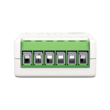
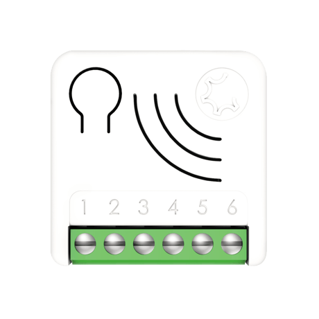
META Double Switch -L 7 is an ON/OFF control device designed to independently control two separate loads, suited for being controlled by both remote and local switches.


1 - IN1_TYPE
Define the 1st input typeSize: 1 byte
Default: 1
Minimum: 0
Maximum: 2
Possible values
| From | To | Desription |
|---|---|---|
| 0 | 0 | No switch input |
| 1 | 1 | Momentary switch (button) |
| 2 | 2 | Toggle switch |
2 - IN2_TYPE
Define the 2nd input typeSize: 1 byte
Default: 1
Minimum: 0
Maximum: 2
Possible values
| From | To | Desription |
|---|---|---|
| 0 | 0 | No switch input |
| 1 | 1 | Momentary switch (button) |
| 2 | 2 | Toggle switch |
10 - IN1_TOGGLE
Define which events on the input 1 toggle output 1.Size: 1 byte
Default: 15
Minimum: 0
Maximum: 31
Possible values
| From | To | Desription |
|---|---|---|
| 0 | 0 | Disabled |
| 1 | 1 | 1 click |
| 2 | 2 | 2 clicks |
| 4 | 4 | 3 clicks |
| 8 | 8 | Hold down |
| 16 | 16 | Up |
11 - IN1_ON_EXCLUSION
Define which events on the input 1 do not switch-On output 1.Size: 1 byte
Default: 0
Minimum: 0
Maximum: 31
Possible values
| From | To | Desription |
|---|---|---|
| 0 | 0 | Disable |
| 1 | 1 | 1 click |
| 2 | 2 | 2 clicks |
| 4 | 4 | 3 clicks |
| 8 | 8 | Hold down |
| 16 | 16 | Up |
12 - IN1_OFF_EXCLUSION
Define which events on the input 1 do not switch-Off output 1.Size: 1 byte
Default: 0
Minimum: 0
Maximum: 31
Possible values
| From | To | Desription |
|---|---|---|
| 0 | 0 | Disable |
| 1 | 1 | 1 click |
| 2 | 2 | 2 clicks |
| 4 | 4 | 3 clicks |
| 8 | 8 | Hold down |
| 16 | 16 | Up |
15 - IN2_TOGGLE
Define which events on the input 2 toggle output 2.Size: 1 byte
Default: 15
Minimum: 0
Maximum: 31
Possible values
| From | To | Desription |
|---|---|---|
| 0 | 0 | Disable |
| 1 | 1 | 1 click |
| 2 | 2 | 2 clicks |
| 4 | 4 | 3 clicks |
| 8 | 8 | Hold down |
| 16 | 16 | Up |
16 - IN2_ON_EXCLUSION
Define which events on the input 2 do not switch-On output 2.Size: 1 byte
Default: 0
Minimum: 0
Maximum: 31
Possible values
| From | To | Desription |
|---|---|---|
| 0 | 0 | Disable |
| 1 | 1 | 1 click |
| 2 | 2 | 2 clicks |
| 4 | 4 | 3 clicks |
| 8 | 8 | Hold down |
| 16 | 16 | Up |
17 - IN2_OFF_EXCLUSION
Define which events on the input 2 do not switch-Off output 2.Size: 1 byte
Default: 0
Minimum: 0
Maximum: 31
Possible values
| From | To | Desription |
|---|---|---|
| 0 | 0 | Disable |
| 1 | 1 | 1 click |
| 2 | 2 | 2 clicks |
| 4 | 4 | 3 clicks |
| 8 | 8 | Hold down |
| 16 | 16 | Up |
21 - OUT1_TYPE
Define the 1st output type.Size: 1 byte
Default: 0
Minimum: 0
Maximum: 1
Possible values
| From | To | Desription |
|---|---|---|
| 0 | 0 | Direct load or normally Open relay |
| 1 | 1 | Normally Closed relay |
22 - OUT2_TYPE
Define the 2nd output type.Size: 1 byte
Default: 0
Minimum: 0
Maximum: 1
Possible values
| From | To | Desription |
|---|---|---|
| 0 | 0 | Direct load or normally Open relay |
| 1 | 1 | Normally Closed relay |
23 - STARTUP_OUT1
Define the 1st output level on startup (status of the device following a restart)Size: 1 byte
Default: 2
Minimum: 0
Maximum: 3
Possible values
| From | To | Desription |
|---|---|---|
| 0 | 0 | OFF |
| 1 | 1 | ON |
| 2 | 2 | Previous status |
| 3 | 3 | equal to input (ON if input close, OFF if input open) |
24 - STARTUP_OUT2
Define the 2nd output level on startup (status of the device following a restart)Size: 1 byte
Default: 2
Minimum: 0
Maximum: 3
Possible values
| From | To | Desription |
|---|---|---|
| 0 | 0 | OFF |
| 1 | 1 | ON |
| 2 | 2 | Previous status |
| 3 | 3 | equal to input (ON if input close, OFF if input open) |
25 - LOCAL SCENE
Define the Local scene configuration.Size: 1 byte
Default: 0
Minimum: 0
Maximum: 2
Possible values
| From | To | Desription |
|---|---|---|
| 0 | 0 | independent channel (External switch 11 controls output 1 load and external switch 12 controls output 2 load) |
| 1 | 1 | never both on (Both outputs can be OFF but they can never be ON simultaneously) |
| 2 | 2 | Sequencing (Outputs are toggled in this order: both loads ON, only load 1 ON, only load 2 ON, both loads OFF) |
30 - TIMER_CH1_SETUP
Define which trigger event on the Channel 1 activate its timers when output 1 has changedSize: 1 byte
Default: 0
Minimum: 0
Maximum: 127
Possible values
| From | To | Desription |
|---|---|---|
| 0 | 0 | Disabled |
| 1 | 1 | 1 click |
| 2 | 2 | 2 clicks |
| 4 | 4 | 3 clicks |
| 8 | 8 | Hold down |
| 16 | 16 | Up |
| 32 | 32 | Network (status change trigger by gateway or other devices in the Z-Wave network). |
| 64 | 64 | System (based on the startup status, or other timer event). |
31 - OFF_EP1_TIMEOUT
Time in tenth of seconds after which the output on Channel 1 will be switched Off.Size: 4 bytes
Default: 0
Minimum: 0
Maximum: 360000
Possible values
| From | To | Desription |
|---|---|---|
| 0 | 360000 | Specific time expressed in tenth of seconds for Status change. |
32 - ON_EP1_TIMEOUT
Time in tenth of seconds after which the output on Channel 1 will be switched OnSize: 4 bytes
Default: 0
Minimum: 0
Maximum: 360000
Possible values
| From | To | Desription |
|---|---|---|
| 0 | 360000 | Specific time expressed in tenth of seconds for Status change. |
33 - TIMER_CH2_SETUP
Define which trigger events on the Channel 2 activate its timers when output 2 has changedSize: 1 byte
Default: 0
Minimum: 0
Maximum: 127
Possible values
| From | To | Desription |
|---|---|---|
| 0 | 0 | Disabled |
| 1 | 1 | 1 click |
| 2 | 2 | 2 clicks |
| 4 | 4 | 3 clicks |
| 8 | 8 | Hold down |
| 16 | 16 | Up |
| 32 | 32 | Network (status change trigger by gateway or other devices in the Z-Wave network) |
| 64 | 64 | System (based on the startup status, or other timer event) |
34 - OFF_EP2_TIMEOUT
Time in tenth of seconds after which the output on Channel 2 will be switched OffSize: 4 bytes
Default: 0
Minimum: 0
Maximum: 360000
Possible values
| From | To | Desription |
|---|---|---|
| 0 | 360000 | Specific time expressed in tenth of seconds for Status change. |
35 - ON_EP2_TIMEOUT
Time in tenth of seconds after which the output on Channel 2 will be switched OnSize: 4 bytes
Default: 0
Minimum: 0
Maximum: 360000
Possible values
| From | To | Desription |
|---|---|---|
| 0 | 360000 | Specific time expressed in tenth of seconds for Status change. |
40 - G1_EP1_SETUP
Define which events on the input 1 control G1 association group on Channel 1.Size: 1 byte
Default: 1
Minimum: 0
Maximum: 31
Possible values
| From | To | Desription |
|---|---|---|
| 0 | 0 | No control |
| 1 | 1 | 1 click |
| 2 | 2 | 2 clicks |
| 4 | 4 | 3 clicks |
| 8 | 8 | Hold down |
| 16 | 16 | Up |
41 - G2_EP1_SETUP
Define which events on the input 1 control G2 association group on Channel 1.Size: 1 byte
Default: 2
Minimum: 0
Maximum: 31
Possible values
| From | To | Desription |
|---|---|---|
| 0 | 0 | No control |
| 1 | 1 | 1 click |
| 2 | 2 | 2 clicks |
| 4 | 4 | 3 clicks |
| 8 | 8 | Hold down |
| 16 | 16 | Up |
42 - G1_EP2_SETUP
Define which events on the input 2 control G1 association group on Channel 2.Size: 1 byte
Default: 2
Minimum: 0
Maximum: 31
Possible values
| From | To | Desription |
|---|---|---|
| 0 | 0 | No control |
| 1 | 1 | 1 click |
| 2 | 2 | 2 clicks |
| 4 | 4 | 3 clicks |
| 8 | 8 | Hold down |
| 16 | 16 | Up |
43 - G2_EP2_SETUP
Define which events on the input 2 control G2 association group on Channel 2.Size: 1 byte
Default: 2
Minimum: 0
Maximum: 31
Possible values
| From | To | Desription |
|---|---|---|
| 0 | 0 | No control |
| 1 | 1 | 1 click |
| 2 | 2 | 2 clicks |
| 4 | 4 | 3 clicks |
| 8 | 8 | Hold down |
| 16 | 16 | Up |
44 - G1_EP1_ASS_VALUE
The value used to control G1 association group on Channel 1.Size: 1 byte
Default: 101
Minimum: 0
Maximum: 102
Possible values
| From | To | Desription |
|---|---|---|
| 0 | 99 | Specific value |
| 100 | 100 | ON |
| 101 | 101 | Propagate (output 1 status to the associated device) |
| 102 | 102 | Toggle remote (change status ON/OFF of associated devices) |
45 - G2_EP1_ASS_VALUE
The value used to control G2 association group on Channel 1.Size: 1 byte
Default: 101
Minimum: 0
Maximum: 102
Possible values
| From | To | Desription |
|---|---|---|
| 0 | 99 | Specific value |
| 100 | 100 | ON |
| 101 | 101 | Propagate (output 1 status to the associated device) |
| 102 | 102 | Toggle remote (change status ON/OFF of associated devices) |
46 - G1_EP2_ASS_VALUE
The value used to control G1 association group on Channel 2.Size: 1 byte
Default: 101
Minimum: 0
Maximum: 102
Possible values
| From | To | Desription |
|---|---|---|
| 0 | 99 | Specific value |
| 100 | 100 | ON |
| 101 | 101 | Propagate (output 2 status to the associated device) |
| 102 | 102 | Toggle remote (change status ON/OFF of associated devices) |
47 - G2_EP2_ASS_VALUE
The value used to control G2 association group on Channel 2.Size: 1 byte
Default: 101
Minimum: 0
Maximum: 102
Possible values
| From | To | Desription |
|---|---|---|
| 0 | 99 | Specific value |
| 100 | 100 | ON |
| 101 | 101 | Propagate (output 2 status to the associated device) |
| 102 | 102 | Toggle remote (change status ON/OFF of associated devices) |
60 - SCENE_SETUP
Define which event on the input trigger a central scene notification.Size: 1 byte
Default: 31
Minimum: 0
Maximum: 31
Possible values
| From | To | Desription |
|---|---|---|
| 0 | 0 | None |
| 1 | 1 | 1 click |
| 2 | 2 | 2 clicks |
| 4 | 4 | 3 clicks |
| 8 | 8 | Hold down |
| 16 | 16 | Up |
70 - E_REPORT_DELAY
Time in minutes after which the next Energy report will be sentSize: 1 byte
Default: 10
Minimum: 1
Maximum: 120
Possible values
| From | To | Desription |
|---|---|---|
| 1 | 120 | Report generation in a specific time in minutes |
71 - W_REPORT_DELAY
Time in minutes after which the next Energy report will be sentSize: 1 byte
Default: 10
Minimum: 1
Maximum: 120
Possible values
| From | To | Desription |
|---|---|---|
| 1 | 120 | Report generation in a specific time in minutes |
75 - W_ISTANT_REPORT
The percentage change from the last sent report that trigger a new Power reportSize: 1 byte
Default: 30
Minimum: 0
Maximum: 100
Possible values
| From | To | Desription |
|---|---|---|
| 0 | 0 | No report is sent (for any power change) |
| 1 | 100 | The percentage of Power change from the last sent report that triggers a new meter report sequence |
All META Serie 7 devices are compatible with all Z-Wave™/Z-Wave Plus™ certified controllers. The devices support both the Network Wide Inclusion mechanism (which offers the ability to be included in a network, even if the device is not directly connected to the controller) and Normal Inclusion. By default, the inclusion procedure starts in Normal Inclusion mode and after a short timeout the procedure continues in Network Wide Inclusion mode that lasts for about 20 Seconds. Only a controller can add the device into the network. After activating the inclusion function by the controller, the device can be added by setting it in Learn Mode.
Only a controller can remove the device from the network. After activating the exclusion function by the controller, the device can be removed by setting it in Learn Mode. The procedure of exclusion can be activated by Removing a node from the Z-Wave™ network and executing 1 or 3 click on the integrated button; as soon as the exclusion initiates, the LED indicator starts a sequence of RED-BLUE blinks. The device is excluded from the network when the LED status indicator is solid RED and the App_status in the interface is OK.
Reset to the factory settings The device can be reset to the original factory settings with 6 consecutive clicks on the integrated button. After the reset is completed, the device will reboot and a RED solid led is showed. Please use this procedure only when the network primary controller is missing or otherwise inoperable. INFO: If the reset is performed while the device is still part of a network, it notifies the other devices that it has been removed (Device Reset Locally Notification).
Timer Management An independent timer for each channel can be set when switching On and/or Off. It also possible to define which event will start the timer (for example only the change on the output due to double clicks). Power consumption management The device is equipped with a very precise power metering functionality, therefore you can easily monitor the instantaneous power and cumulated energy for each channel. Offline setup Mode The device has a unique feature that allows to configure some parameters without using any user interface. This feature enables the professional user to setup the main features of the device in the field even if the device is not included in a Z-Wave™ Network. When the device will be included in the network all these configuration parameters will be maintained. Central Scene Notification Supports Central Scene Notification all the events described in the table will be notified with a Central Scene Notification Report to the Lifeline. The events that trigger a Central Scene Notification Report can be customized with the configuration parameter in the Central Scene Notification Parameter section.
Page 38 - The SmartStart QR and the full DSK string code can be found on the back of the device. The PIN is the first group of 5 digits printed underlined. If you plan to use the DSK, it is important that you take a picture of the label and keep it in a safe place.