Inovelli
Smart 2-1 Switch(On/Off or Dimmer)
VZW31-SN
Multilevel Switch DT
HW: 01 FW: 01.00
ZGM230SA
7.18.1
0x031E (798)
N/A
0x0015 (21)
ZC14-23030203
2023-03-01 16:50:11
N/A
Enhanced End Node 232
Always On Slave
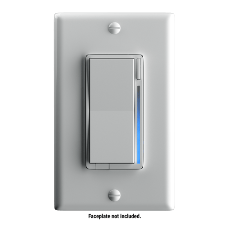
Introducing the first Z-Wave™ 800 Series Light Switch with Long Range, Multi-Tap Scene Control and LED Notifications powered by Inovelli.


1 - Dimming Speed (Dimming Up)
Now in 100ms. This changes the speed in which the attached light dims up or down. A setting of 0 should turn the light immediately on or off (almost like an on/off switch). Increasing the value should slow down the transition speed.Size: 1 byte
Default: 25
Minimum: 0
Maximum: 254
Possible values
| From | To | Desription |
|---|---|---|
| 0 | 100 | 0-10000 ms |
| 101 | 160 | 1-59 seconds |
| 161 | 254 | 1-93 minutes |
2 - Dimming Speed (From Switch) (Dimming Up)
Now in 100ms. This changes the speed in which the attached light dims up or down when controlled from the physical switch. A setting of 0 should turn the light immediately on or off (almost like an on/off switch). Increasing the value should slow down the transition speed. A setting of 255 should keep this in sync with parameter 1.Size: 1 byte
Default: 255
Minimum: 0
Maximum: 255
Possible values
| From | To | Desription |
|---|---|---|
| 0 | 100 | 0-10000 ms |
| 101 | 160 | 1-59 seconds |
| 161 | 254 | 1-93 minutes |
| 255 | 255 | Keep in sync with parameter 1 |
3 - Ramp Rate (OFF to ON)
Now in 100ms. This changes the speed in which the attached light dims up or down when controlled from the physical switch. A setting of 0 should turn the light immediately on or off (almost like an on/off switch). Increasing the value should slow down the transition speed. A setting of 255 should keep this in sync with parameter 1.Size: 1 byte
Default: 255
Minimum: 0
Maximum: 255
Possible values
| From | To | Desription |
|---|---|---|
| 0 | 100 | 0-10000 ms |
| 101 | 160 | 1-59 seconds |
| 161 | 254 | 1-93 minutes |
| 255 | 255 | Keep in sync with parameter 1 |
4 - Ramp Rate (From Switch) (OFF to ON)
Now in 100ms. This changes the speed in which the attached light dims up or down when controlled from the physical switch. A setting of 0 should turn the light immediately on or off (almost like an on/off switch). Increasing the value should slow down the transition speed. A setting of 255 should keep this in sync with parameter 1.Size: 1 byte
Default: 255
Minimum: 0
Maximum: 255
Possible values
| From | To | Desription |
|---|---|---|
| 0 | 100 | 0-10000 ms |
| 101 | 160 | 1-59 seconds |
| 161 | 254 | 1-93 minutes |
| 255 | 255 | Keep in sync with parameter 1 |
5 - Dimming Speed (Dimming down)
Now in 100ms. This changes the speed in which the attached light dims up or down when controlled from the physical switch. A setting of 0 should turn the light immediately on or off (almost like an on/off switch). Increasing the value should slow down the transition speed. A setting of 255 should keep this in sync with parameter 1.Size: 1 byte
Default: 255
Minimum: 0
Maximum: 255
Possible values
| From | To | Desription |
|---|---|---|
| 0 | 100 | 0-10000 ms |
| 101 | 160 | 1-59 seconds |
| 161 | 254 | 1-93 minutes |
| 255 | 255 | Keep in sync with parameter 1 |
6 - Dimming Speed (From Switch) (Dimming Down)
Now in 100ms. This changes the speed in which the attached light dims up or down when controlled from the physical switch. A setting of 0 should turn the light immediately on or off (almost like an on/off switch). Increasing the value should slow down the transition speed. A setting of 255 should keep this in sync with parameter 1.Size: 1 byte
Default: 255
Minimum: 0
Maximum: 255
Possible values
| From | To | Desription |
|---|---|---|
| 0 | 100 | 0-10000 ms |
| 101 | 160 | 1-59 seconds |
| 161 | 254 | 1-93 minutes |
| 255 | 255 | Keep in sync with parameter 1 |
7 - Ramp Rate (ON to OFF)
Now in 100ms. This changes the speed in which the attached light dims up or down when controlled from the physical switch. A setting of 0 should turn the light immediately on or off (almost like an on/off switch). Increasing the value should slow down the transition speed. A setting of 255 should keep this in sync with parameter 1.Size: 1 byte
Default: 255
Minimum: 0
Maximum: 255
Possible values
| From | To | Desription |
|---|---|---|
| 0 | 100 | 0-10000 ms |
| 101 | 160 | 1-59 seconds |
| 161 | 254 | 1-93 minutes |
| 255 | 255 | Keep in sync with parameter 1 |
8 - Ramp Rate (From Switch) (ON to OFF)
Now in 100ms. This changes the speed in which the attached light dims up or down when controlled from the physical switch. A setting of 0 should turn the light immediately on or off (almost like an on/off switch). Increasing the value should slow down the transition speed. A setting of 255 should keep this in sync with parameter 1.Size: 1 byte
Default: 255
Minimum: 0
Maximum: 255
Possible values
| From | To | Desription |
|---|---|---|
| 0 | 100 | 0-10000 ms |
| 101 | 160 | 1-59 seconds |
| 161 | 254 | 1-93 minutes |
| 255 | 255 | Keep in sync with parameter 1 |
9 - Minimum Level
The minimum level that the dimmer allows the bulb to be dimmed to. Useful when the user has a bulb that does not turn on at a lower levelSize: 1 byte
Default: 1
Minimum: 1
Maximum: 54
Possible values
| From | To | Desription |
|---|---|---|
| 1 | 54 | percent |
10 - Maximum Level
The maximum level that the dimmer allows the bulb to be dimmed to. Useful when the user has an LED bulb that reaches its maximum level before the dimmer value of 99Size: 1 byte
Default: 99
Minimum: 55
Maximum: 99
Possible values
| From | To | Desription |
|---|---|---|
| 55 | 99 | percent |
11 - Invert Switch
Inverts the orientation of the switch. Useful when the switch is installed upside down. Essentially up becomes down and down becomes up. Need to ensure that the LED bar also flips upside down so that the direction of the dimming is correct.Size: 1 byte
Default: 0
Minimum: 0
Maximum: 1
Possible values
| From | To | Desription |
|---|---|---|
| 0 | 0 | Disabled |
| 1 | 1 | Enabled |
12 - Auto Off Timer
Automatically turns the switch off after this many seconds. When the switch is turned on a timer is started that is the duration of this setting. When the timer expires, the switch is turned off.Size: 2 bytes
Default: 0
Minimum: 0
Maximum: 32767
Possible values
| From | To | Desription |
|---|---|---|
| 0 | 0 | Off |
| 1 | 32767 | seconds |
13 - Default Level (Local)
Default level for the dimmer when it is powered on from the local switch. A setting of 0 means that the switch will return to the level that it was on before it was turned off.Size: 1 byte
Default: 0
Minimum: 0
Maximum: 99
Possible values
| From | To | Desription |
|---|---|---|
| 0 | 0 | Previous Level |
| 1 | 99 | percent |
14 - Default Level (Z-Wave)
Default level for the dimmer when it is powered on from a Z-Wave command. A setting of 0 means that the switch will return to the level that it was on before it was turned off.Size: 1 byte
Default: 0
Minimum: 0
Maximum: 99
Possible values
| From | To | Desription |
|---|---|---|
| 0 | 0 | Previous Level |
| 1 | 99 | percent |
15 - State After Power Restored
The state the switch should return to once power is restored after power failure.Size: 1 byte
Default: 100
Minimum: 0
Maximum: 100
Possible values
| From | To | Desription |
|---|---|---|
| 0 | 0 | OFF |
| 1 | 99 | 1-99 level |
| 100 | 100 | Previous |
17 - Load Level Indicator Timeout
Shows the level that the load is at for x number of seconds after the load is adjusted and then returns to the Default LED state. By default, it should always show the level when the load is ON (value 11).Size: 1 byte
Default: 11
Minimum: 0
Maximum: 11
Possible values
| From | To | Desription |
|---|---|---|
| 0 | 0 | Always Off |
| 1 | 1 | Turns on for 1 second after level is adjusted |
| 2 | 2 | Turns on for 2 seconds after level is adjusted |
| 3 | 3 | Turns on for 3 seconds after level is adjusted |
| 9 | 9 | Turns on for 9 seconds after level is adjusted |
| 10 | 10 | Turns on for 10 seconds after level is adjusted |
| 11 | 11 | Always On |
18 - Active Power Reports
The power level change that will result in a new power report being sent. The value is a percentage of the previous report.Size: 1 byte
Default: 10
Minimum: 0
Maximum: 100
Possible values
| From | To | Desription |
|---|---|---|
| 0 | 0 | no report |
| 1 | 100 | percentage of previous report |
19 - Periodic Power & Energy Reports
Time period between consecutive power & energy reports being sent (in seconds). The timer is reset after each report is sent.Size: 2 bytes
Default: 3600
Minimum: 0
Maximum: 32767
Possible values
| From | To | Desription |
|---|---|---|
| 30 | 32767 | Time in seconds |
20 - Energy Reports
The energy level change that will result in a new energy report being sent. This means that how many kWh of energy is added will send energy report.Size: 2 bytes
Default: 10
Minimum: 0
Maximum: 32767
Possible values
| From | To | Desription |
|---|---|---|
| 0 | 0 | no report |
| 1 | 32767 | 0.01kWh - 327.67kWh change |
21 - Power Type
Set Power TypeSize: 1 byte
Default: 1
Minimum: 0
Maximum: 1
Possible values
| From | To | Desription |
|---|---|---|
| 0 | 0 | Non Neutral |
| 1 | 1 | Neutral |
22 - Switch Type
Set Switch TypeSize: 1 byte
Default: 0
Minimum: 0
Maximum: 3
Possible values
| From | To | Desription |
|---|---|---|
| 0 | 0 | Load only |
| 1 | 1 | Double control |
| 2 | 2 | AUX |
| 3 | 3 | Single full wave (Only OnOff Mode) |
50 - Button Delay Time
Adjust the delay used in waiting for a scene commandSize: 1 byte
Default: 5
Minimum: 0
Maximum: 9
Possible values
| From | To | Desription |
|---|---|---|
| 0 | 0 | 0ms (Only Up and Down delay time 0ms, config delay time 500 ms) |
| 1 | 1 | 100ms |
| 2 | 2 | 200ms |
| 3 | 3 | 300ms (Up, Down and config delay time 300ms ) |
| 4 | 4 | 400ms (Up, Down and config delay time 400ms ) |
| 5 | 5 | 500ms (Up, Down and config delay time 500ms ) |
| 6 | 6 | 600ms (Up, Down and config delay time 600ms ) |
| 7 | 7 | 700ms (Up, Down and config delay time 700ms ) |
| 8 | 8 | 800ms (Up, Down and config delay time 800ms ) |
| 9 | 9 | 900ms (Up, Down and config delay time 900ms ) |
52 - Use Smart Bulb
It determines whether or not the dimmer is loaded a smart bulb.Size: 1 byte
Default: 1
Minimum: 0
Maximum: 1
Possible values
| From | To | Desription |
|---|---|---|
| 0 | 0 | Smart Bulb Mode Disable |
| 1 | 1 | Smart Bulb Mode Enable |
53 - Double Tap Up to Max
Double tap the "up" button to change level to 100%.Size: 1 byte
Default: 0
Minimum: 0
Maximum: 1
Possible values
| From | To | Desription |
|---|---|---|
| 0 | 0 | Disable (default) |
| 1 | 1 | Enable |
54 - Double Tap Down to Min
Double tap the "down" button to change level to 1%.Size: 1 byte
Default: 0
Minimum: 0
Maximum: 1
Possible values
| From | To | Desription |
|---|---|---|
| 0 | 0 | Disable (default) |
| 1 | 1 | Enable |
59 - Association Behavior
Association Behavior When should the switch send commands to associated devices?Size: 1 byte
Default: 1
Minimum: 0
Maximum: 3
Possible values
| From | To | Desription |
|---|---|---|
| 0 | 0 | Disable |
| 1 | 1 | Local |
| 2 | 2 | Z-wave Hub |
| 3 | 3 | Local + z-wave hub |
64 - LED1 Strip Effect
Byte1=Choose color, Byte2=Choose brightness level, Byte3=Choose duration, Byte4=Choose effectSize: 4 bytes
Default: 0
Minimum: 0
Maximum: 4294967295
Possible values
| From | To | Desription |
|---|---|---|
| 0 | 4294967295 | Byte1=Choose color, Byte2=Choose brightness level, Byte3=Choose duration, Byte4=Choose effect |
69 - LED2 Strip Effect
Byte1=Choose color, Byte2=Choose brightness level, Byte3=Choose duration, Byte4=Choose effectSize: 4 bytes
Default: 0
Minimum: 0
Maximum: 4294967295
Possible values
| From | To | Desription |
|---|---|---|
| 0 | 4294967295 | Byte1=Choose color, Byte2=Choose brightness level, Byte3=Choose duration, Byte4=Choose effect |
74 - LED3 Strip Effect
Byte1=Choose color, Byte2=Choose brightness level, Byte3=Choose duration, Byte4=Choose effectSize: 4 bytes
Default: 0
Minimum: 0
Maximum: 4294967295
Possible values
| From | To | Desription |
|---|---|---|
| 0 | 4294967295 | Byte1=Choose color, Byte2=Choose brightness level, Byte3=Choose duration, Byte4=Choose effect |
79 - LED4 Effect
LED4 EffectSize: 4 bytes
Default: 0
Minimum: 0
Maximum: 4294967295
Possible values
| From | To | Desription |
|---|---|---|
| 0 | 4294967295 | Byte1=Choose color, Byte2=Choose brightness level, Byte3=Choose duration, Byte4=Choose effect |
84 - LED5 Strip Effect
Byte1=Choose color, Byte2=Choose brightness level, Byte3=Choose duration, Byte4=Choose effectSize: 4 bytes
Default: 0
Minimum: 0
Maximum: 4294967295
Possible values
| From | To | Desription |
|---|---|---|
| 0 | 4294967295 | Byte1=Choose color, Byte2=Choose brightness level, Byte3=Choose duration, Byte4=Choose effect |
89 - LED6 Strip Effect
Byte1=Choose color, Byte2=Choose brightness level, Byte3=Choose duration, Byte4=Choose effectSize: 4 bytes
Default: 0
Minimum: 0
Maximum: 4294967295
Possible values
| From | To | Desription |
|---|---|---|
| 0 | 4294967295 | Byte1=Choose color, Byte2=Choose brightness level, Byte3=Choose duration, Byte4=Choose effect |
94 - LED7 Strip Effect
Byte1=Choose color, Byte2=Choose brightness level, Byte3=Choose duration, Byte4=Choose effectSize: 4 bytes
Default: 0
Minimum: 0
Maximum: 4294967295
Possible values
| From | To | Desription |
|---|---|---|
| 0 | 4294967295 | Byte1=Choose color, Byte2=Choose brightness level, Byte3=Choose duration, Byte4=Choose effect |
95 - Default ALL LED Strip Color (When On)
This is the color of the LED strip in a hex representation.Size: 1 byte
Default: 170
Minimum: 0
Maximum: 255
Possible values
| From | To | Desription |
|---|---|---|
| 0 | 255 | hex color |
96 - Default ALL LED Strip Color (When Off)
This is the color of the LED strip in a hex representation.Size: 1 byte
Default: 170
Minimum: 0
Maximum: 255
Possible values
| From | To | Desription |
|---|---|---|
| 0 | 255 | hex color |
97 - Default ALL LED Strip Intensity
This is the intensity of the LED strip.Size: 1 byte
Default: 33
Minimum: 0
Maximum: 100
Possible values
| From | To | Desription |
|---|---|---|
| 0 | 0 | Off |
| 10 | 10 | Low |
| 50 | 50 | Mid |
| 100 | 100 | High |
98 - Default ALL LED Strip Intensity (When OFF)
This is the intensity of the LED strip.Size: 1 byte
Default: 1
Minimum: 0
Maximum: 100
Possible values
| From | To | Desription |
|---|---|---|
| 0 | 0 | Off |
| 10 | 10 | Low |
| 50 | 50 | Mid |
| 100 | 100 | High |
99 - ALL LED Strip Effect
Byte1=Choose color, Byte2=Choose brightness level, Byte3=Choose duration, Byte4=Choose effectSize: 4 bytes
Default: 0
Minimum: 0
Maximum: 4294967295
Possible values
| From | To | Desription |
|---|---|---|
| 0 | 4294967295 | Byte1=Choose color, Byte2=Choose brightness level, Byte3=Choose duration, Byte4=Choose effect |
123 - Aux Switch Scenes
Send Different Central Scene numbers for aux switch? See central scene section below.Size: 1 byte
Default: 0
Minimum: 0
Maximum: 1
Possible values
| From | To | Desription |
|---|---|---|
| 0 | 0 | Disable |
| 1 | 1 | Enable |
158 - Dimmer/OnOff Mode
Set Dimmer/OnOff ModeSize: 1 byte
Default: 1
Minimum: 0
Maximum: 1
Possible values
| From | To | Desription |
|---|---|---|
| 0 | 0 | Dimmer Mode |
| 1 | 1 | OnOffMode |
159 - OnlyOneLed Mode
This parameter can be set only in OnOff mode. In Dimmer mode, The value is invalid.Size: 1 byte
Default: 0
Minimum: 0
Maximum: 1
Possible values
| From | To | Desription |
|---|---|---|
| 0 | 0 | Disable All Led show |
| 1 | 1 | Enable one led show |
160 - Firmware progress LED
Whether to display the effect during FLASH updateSize: 1 byte
Default: 1
Minimum: 0
Maximum: 1
Possible values
| From | To | Desription |
|---|---|---|
| 0 | 0 | Disable |
| 1 | 1 | Enable (default) |
161 - Relay Click In OnOff Mode
Set Relay Click behavior in OnOff ModeSize: 1 byte
Default: 0
Minimum: 0
Maximum: 1
Possible values
| From | To | Desription |
|---|---|---|
| 0 | 0 | Audible Click for ON/OFF Mode ON |
| 1 | 1 | Audible Click for ON/OFF Mode OFF |
162 - Double tap to clear notification
Enable/Disable clearing notifications with double tapSize: 1 byte
Default: 0
Minimum: 0
Maximum: 1
Possible values
| From | To | Desription |
|---|---|---|
| 0 | 0 | Enabled (Default) |
| 1 | 1 | Disabled |
The switch will automatically start the inclusion process when power is restored. To indicate the switch is in inclusion mode, the LED Bar will pulse blue. If the LED Bar is not pulsing, tap the config button 3x rapidly or pull the air-gap out and push it back in. Start the Z-Wave inclusion process on your hub at any time. If successful, the LED Bar will flash green and if unsuccessful, it will flash red.
If the switch is unsuccessful during inclusion, you can exclude the switch by putting your gateway in exclusion mode and pressing the config button three times. The LED Bar will pulse blue and then flash green if successful or red if not.
To factory reset your device, hold down on the top part of the paddle as well as the Configuration / Favorites Button for 20 seconds until the LED Bar turns red and let go of both. The switch should blink red a few times indicating it has been factory reset. You may also use a certified Z-Wave controller to remove the device from your network to factory default. Only use these procedures in the event that the primary controller is missing or otherwise inoperable.
This switch has animated notifications that can alert you of certain events (garage door left open, doors unlocked, etc), multi-tap scene control from both the switch and, if in a multi-way setting, from an add-on/auxiliary switch. It also has our invention, Smart Bulb Mode, which will lock power to your smart bulb and digitally turn on/off/dim your smart bulb. Please note, while these features are on the switch, they must also be supported by the hub/gateway.
The DSK information required for some inclusion methods can be found either on the product (QR Code located at the bottom front-left of the switch), on the back of the box (QR Code located at the bottom right), or on the insert inside the box.
| Type | Value(s) |
|---|