Heatit
Heatit ZM Dimmer
ZM Dimmer
Multilevel Switch DT
HW: 01 FW: 01.00:02.01
EFR32ZG23A
7.18.1
0x019B (411)
N/A
0x0021 (33)
ZC14-23040223
2023-04-05 08:21:10
N/A
Enhanced End Node 232
Always On End Node
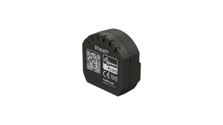
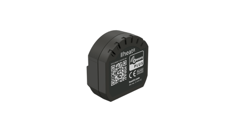
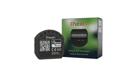
Heatit ZM Dimmer is an inwall dimmer for installation in European electrical wall boxes. The dimmer enables the user to control light sources from the Z-Wave™ network and/or an external switch.
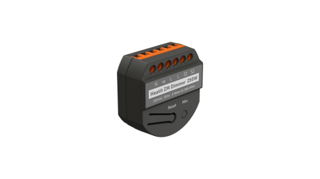
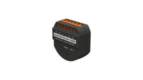


1 - Power restore level
The state the dimmer should return to once power is restored after a power failure.Size: 1 byte
Default: 100
Minimum: 0
Maximum: 100
Possible values
| From | To | Desription |
|---|---|---|
| 0 | 0 | Off. |
| 1 | 99 | 1%-99%. |
| 100 | 100 | Returns to level before power outage (Default). |
2 - Switch ON level
Defines the dimming level when restored from the OFF state.Size: 1 byte
Default: 0
Minimum: 0
Maximum: 99
Possible values
| From | To | Desription |
|---|---|---|
| 0 | 0 | OFF (Default) |
| 1 | 99 | 1%-99%. |
3 - Automatic turn OFF Duration
Time for the dimmer to turn off automatically after turning it on.Size: 4 bytes
Default: 0
Minimum: 0
Maximum: 86400
Possible values
| From | To | Desription |
|---|---|---|
| 0 | 0 | Auto OFF disabled (Default). |
| 1 | 86400 | seconds |
4 - Automatic turn ON Duration
Time for the dimmer to turn on automatically after turning it off.Size: 4 bytes
Default: 0
Minimum: 0
Maximum: 86400
Possible values
| From | To | Desription |
|---|---|---|
| 0 | 0 | Auto ON disabled (Default). |
| 1 | 86400 | seconds |
5 - Turn off delay time
The time it takes before the dimmer turns off after turning it off.Size: 1 byte
Default: 0
Minimum: 0
Maximum: 60
Possible values
| From | To | Desription |
|---|---|---|
| 0 | 0 | Disabled (Default). |
| 1 | 60 | seconds |
6 - S1 functionality
Decide the S1 switch functionality.Size: 1 byte
Default: 0
Minimum: 0
Maximum: 3
Possible values
| From | To | Desription |
|---|---|---|
| 0 | 0 | Single press and hold for dimming. |
| 0 | 0 | Double press for 100%. |
| 0 | 0 | Triple press for inclusion. |
| 1 | 1 | Scene controller. |
| 2 | 2 | Scene controller and Dimming |
| 3 | 3 | Disabled. |
7 - S2 functionality
Decide the S2 switch functionality.Size: 1 byte
Default: 1
Minimum: 0
Maximum: 3
Possible values
| From | To | Desription |
|---|---|---|
| 0 | 0 | Single press and hold for dimming. |
| 0 | 0 | Double press for scene controller. |
| 0 | 0 | Triple press for inclusion. |
| 1 | 1 | Scene controller Functionality (Default). |
| 2 | 2 | Scene controller and Dimming |
| 3 | 3 | Disabled. |
8 - Dimming duration
Define how long it takes to dim when using the external switch.Size: 1 byte
Default: 50
Minimum: 0
Maximum: 100
Possible values
| From | To | Desription |
|---|---|---|
| 0 | 0 | Instantly. |
| 1 | 100 | N * 0.1 seconds. (0.1 - 10 seconds) |
9 - Dimmer curve
Choose if the dimmer uses Linear or Logarythmic dimming.Size: 1 byte
Default: 0
Minimum: 0
Maximum: 1
Possible values
| From | To | Desription |
|---|---|---|
| 0 | 0 | Choose the Linear dimming (Default). |
| 1 | 1 | Logarithmic dimming. |
10 - Load dimming mode
Choose the dimming type.Size: 1 byte
Default: 0
Minimum: 0
Maximum: 1
Possible values
| From | To | Desription |
|---|---|---|
| 0 | 0 | Trailing edge (Default). |
| 1 | 1 | Leading edge. |
11 - Maximum dim level
Maximum dim levelSize: 1 byte
Default: 90
Minimum: 2
Maximum: 99
Possible values
| From | To | Desription |
|---|---|---|
| 2 | 99 | percent |
12 - Minimum dim level
Minimum dim levelSize: 1 byte
Default: 15
Minimum: 1
Maximum: 98
Possible values
| From | To | Desription |
|---|---|---|
| 1 | 98 | percent |
13 - Meter report threshold
Threshold to send meter reportSize: 1 byte
Default: 10
Minimum: 0
Maximum: 250
Possible values
| From | To | Desription |
|---|---|---|
| 0 | 0 | Disabled |
| 1 | 250 | Watts |
14 - Meter report interval
Time interval between consecutive meter reports in seconds.Size: 2 bytes
Default: 810
Minimum: 30
Maximum: 65535
Possible values
| From | To | Desription |
|---|---|---|
| 30 | 65535 | seconds |
15 - ON/OFF Functionality
Decide if the connected load should only turn ON/OFF and not dimSize: 1 byte
Default: 0
Minimum: 0
Maximum: 1
Possible values
| From | To | Desription |
|---|---|---|
| 0 | 0 | ON/OFF mode disabled (Default). |
| 1 | 1 | ON/OFF mode enabled. |
The primary controller/gateway has a mode for adding devices. Please refer to your primary controller manual on how to set the primary controller in add mode. The device may only be added from the network if the primary controller is in add mode. When the device is removed from the network, it will NOT revert to factory settings. An always listening node must be powered continuously and reside in a fixed position in the installation to secure the routing table. Adding the device within a 2 meters range from the gateway can minimize faults during the Interview process. Standard (Manual) Add mode is indicated on the device by a blinking green LED. It indicates this for 90 seconds until a timeout occurs, or until the module has been added to the network. Configuration mode can also be cancelled by performing the same procedure used for starting Configuration mode. To start the configuration process, press the reset button 3 times in rapid succession. The LED will light up in solid green for 3 seconds if add is successful. The device is now ready for use with default settings. NB! When the device is removed from the gateway, the parameters are not reset. To reset the parameters, see ”Factory reset”. If inclusion fails, please perform a ”remove device” process and try again. If inclusion fails again, please see “Factory reset”.
The primary controller/gateway has a mode for removing devices. Please refer to your primary controller manual on how to set the primary controller in remove mode. The device may only be removed from the network if the primary controller is in remove mode. When the device is removed from the network, it will NOT revert to factory settings. Standard (Manual) Remove mode is indicated on the device by a blinking green LED. It indicates this for 90 seconds until a timeout occurs, or until the module has been removed from the network. Configuration mode can also be cancelled by performing the same procedure used for starting Configuration mode. To start the configuration process, press the reset button 3 times in rapid succession. The LED will light up in solid green for 3 seconds if remove is successful. The device is now ready for use with default settings. NB! When the device is removed from the gateway, the parameters are not reset. To reset the parameters, see ”Factory reset”.
Factory Reset. Please read this before installation. Press and hold the reset button. After 3 seconds the LED will start to blink green. After 20 seconds the LED will start blinking green rapidly. You may now release the button. If reset was successful the LED will light up in solid green for 3 seconds. Please use this procedure only when the network primary controller is missing or otherwise inoperable.
2 or 3-wire Power metering Overload protection Short circuit protection Surge protection Overheat protection Max. dim level auto-calibration On/off functionality
Paragraph 12. QR-CODE PLACEMENT (DSK) The QR-code is needed when including a device using S2 security or SmartStart. The DSK can be found in the QR-code and is located; • On the product. • In the Quick Guide. • On the packaging box/gift box.
| Type | Value(s) |
|---|
| Group | Type |
|---|---|
| Power Management | Over-load status: Over-load detected |