Heatit
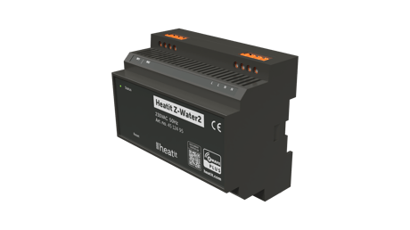
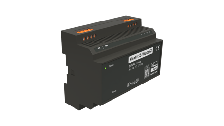
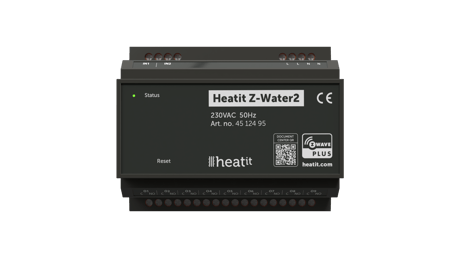
Heatit Z-Water2
Z-Water2
Binary Switch DT
HW: 01 FW: 01.00:02.01
EFR32ZG23A
7.18.1
0x019B (411)
0x0004 (4)
0x020B (523)
ZC14-23060294
2023-06-29 09:13:09
N/A
Enhanced End Node 232
Always On End Node
Heatit Z-Water2 is a DIN-rail regulator for controlling waterbased heating systems. The module clips right onto a DIN-rail and allows you to control your waterbased heating through your Z-Wave™ network.


1 - Input 1 calibration
Manually calibrate input 1Size: 1 byte
Default: 0
Minimum: 196
Maximum: 60
Possible values
| From | To | Desription |
|---|---|---|
| 0 | 0 | 0 |
2 - Input 2 calibration
Manually calibrate input 2Size: 1 byte
Default: 0
Minimum: 196
Maximum: 60
Possible values
| From | To | Desription |
|---|---|---|
| 0 | 0 | 0 |
3 - Temperature report interval
Set temperature report intervalSize: 2 bytes
Default: 870
Minimum: 30
Maximum: 65535
Possible values
| From | To | Desription |
|---|---|---|
| 0 | 0 | 0 |
4 - Temperature report hysteresis
Temperature report hysteresis in CelsiusSize: 1 byte
Default: 10
Minimum: 1
Maximum: 100
Possible values
| From | To | Desription |
|---|---|---|
| 0 | 0 | 0 |
5 - Power restore state
Relay state after power failureSize: 1 byte
Default: 2
Minimum: 0
Maximum: 2
Possible values
| From | To | Desription |
|---|---|---|
| 0 | 0 | 0 |
6 - Inverted outputs
Decide if output should be invertedSize: 1 byte
Default: 0
Minimum: 0
Maximum: 1
Possible values
| From | To | Desription |
|---|---|---|
| 0 | 0 | 0 |
7 - Valve inactivity exercise
Valve exercise periodSize: 1 byte
Default: 0
Minimum: 0
Maximum: 30
Possible values
| From | To | Desription |
|---|---|---|
| 0 | 0 | 0 |
8 - Select antenna type
Choose internal or external antennaSize: 1 byte
Default: 0
Minimum: 0
Maximum: 1
Possible values
| From | To | Desription |
|---|---|---|
| 0 | 0 | 0 |
The primary controller/gateway has a mode for adding devices. Please refer to your primary controller manual on how to set the primary controller in add mode. The device may only be added from the network if the primary controller is in add mode. When the device is removed from the network, it will NOT revert to factory settings. An always listening node must be powered continuously and reside in a fixed position in the installation to secure the routing table. Adding the device within a 2 meter range from the gateway can minimize faults during the Interview process. Standard (Manual) Add mode is indicated on the device by a blinking green LED. It indicates this for 90 seconds until a timeout occurs, or until the device has been added to the network. Configuration mode can also be cancelled by performing the same procedure used for starting Configuration mode. To start the configuration process, press the reset button 3 times in rapid succession. The LED will light up solid green for 3 seconds if add is successful. The device is now ready for use with default settings. NB! When the device is removed from the gateway, the parameters are not reset. To reset the parameters, see Chapter ”Factory reset”. If inclusion fails, please perform a ”remove device” process and try again. If inclusion fails again, please see “Factory reset”.
The primary controller/gateway has a mode for removing devices. Please refer to your primary controller manual on how to set the primary controller in remove mode. The device may only be removed from the network if the primary controller is in remove mode. When the device is removed from the network, it will NOT revert to factory settings. An always listening node must be powered continuously and reside in a fixed position in the installation to secure the routing table. Standard (Manual) Remove mode is indicated on the device by a blinking green LED. It indicates this for 90 seconds until a timeout occurs, or until the device has been removed from the network. Configuration mode can also be cancelled by performing the same procedure used for starting Configuration mode. To start the configuration process, press the reset button 3 times in rapid succession. The LED will light up solid green for 3 seconds if remove is successful. The device is now ready for use with default settings. NB! When the device is removed from the gateway, the parameters are not reset. To reset the parameters, see Chapter ”Factory reset”.
Press and hold the reset button. After 3 seconds the LED will start to blink green. After 20 seconds the LED will start blinking green rapidly. You may now release the button. If reset was successful the LED will light up solid green for 3 seconds.
* External antenna (U.FL female connector) The device allows you to connect a U.FL female connector antenna. This allows the antenna to be wired outside of the installation location in cases of unsatisfactory wireless performance. This connector is placed in the middle of the radio module that is sticking out of the main PCB. See Chapter 22 for a detailed illustration of the placement. Set parameter 8 to 1 to activate this feature. * Automatic valve exercise Valve exercising is beneficial during longer periods of inactivity to ensure the proper operability of the valves and prevent the valves from getting stuck. If not exercised, corrosion or other buildup may result in the valve becoming inoperable or prevent complete closure. To activate this feature see parameter 7. * Can control 230VAC actuators and 24VDC actuators from an external power supply.
Paragraph 11. The QR-Code is needed when including a device using S2 security or SmartStart. The DSK can be found in the QR-Code and is located; • On the product. • In the Quick Guide. • On the packaging box/gift box.
| Type | Value(s) |
|---|
| Sensor type |
|---|
| Air Temperature |