Heatit
Heatit Z-TRM6
Z-TRM6
Thermostat DT
HW: 01 FW: 01.00:02.05
EFR32ZG23A
7.18.1
0x019B (411)
N/A
0x0030 (48)
ZC14-23080311
2023-08-09 07:00:46
N/A
Enhanced End Node 232
Always On End Node
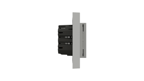
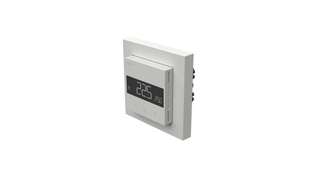
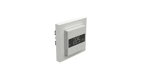
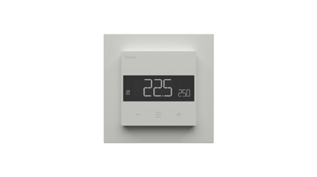
Heatit Z-TRM6 is an electronic thermostat designed for electrical heating. The thermostat can be controlled through your Z-Wave™ network or via the buttons on the front. The thermostat has a user friendly interface. Heatit Z-TRM6 has 3 modes; Heat - Cool and Eco. Heatit Z-TRM6 has active power metering and it gives you real time information about your power consumption.


1 - Disable buttons
Disable buttons, must be enabled through the parameter, or turned back on locally by holding the center and right button for 30 seconds until the display shows "UNLK".Size: 1 byte
Default: 0
Minimum: 0
Maximum: 1
Possible values
| From | To | Desription |
|---|---|---|
| 0 | 0 | Enabled, buttons on the front of the device work. (Default) |
| 1 | 1 | Disabled, buttons on the front of the device are disabled. |
2 - Sensor mode (OPER)
Choose which sensors the thermostat should use for regulation.Size: 1 byte
Default: 1
Minimum: 0
Maximum: 5
Possible values
| From | To | Desription |
|---|---|---|
| 0 | 0 | F, Floor sensor |
| 1 | 1 | A, Internal sensor (Default) |
| 2 | 2 | AF, Internal sensor with floor sensor limitations |
| 3 | 3 | A2, External sensor |
| 4 | 4 | A2F, External sensor with floor sensor limitations |
| 5 | 5 | PWER, Power regulator mode |
3 - Sensor value (SEN)
Select the resistance value of the connected NTC.Size: 1 byte
Default: 0
Minimum: 0
Maximum: 7
Possible values
| From | To | Desription |
|---|---|---|
| 0 | 0 | 10kΩ (Default) |
| 1 | 1 | 12kΩ |
| 2 | 2 | 15kΩ |
| 3 | 3 | 22kΩ |
| 4 | 4 | 33kΩ |
| 5 | 5 | 47kΩ |
| 6 | 6 | 6.8kΩ |
| 7 | 7 | 100kΩ |
4 - Internal sensor min temp limit
Decides the lowest temperature allowed by the thermostat when using sensor mode A.Size: 2 bytes
Default: 50
Minimum: 50
Maximum: 400
Possible values
| From | To | Desription |
|---|---|---|
| 50 | 400 | N * 0.1°C (5°C to 40°C, default is 5°C) |
5 - Floor sensor min temp limit
Decides the lowest temperature allowed by the thermostat when using sensor mode AF, F, A2F.Size: 2 bytes
Default: 50
Minimum: 50
Maximum: 400
Possible values
| From | To | Desription |
|---|---|---|
| 50 | 400 | N * 0.1°C (5°C to 40°C, default is 5°C) |
6 - External sensor min temp limit
Decides the lowest temperature allowed by the thermostat when using sensor mode A2, A2F.Size: 2 bytes
Default: 50
Minimum: 50
Maximum: 400
Possible values
| From | To | Desription |
|---|---|---|
| 50 | 400 | N * 0.1°C (5°C to 40°C, default is 5°C) |
7 - Internal sensor max temp limit
Decide the highest temperature allowed by the thermostat when using sensor mode A.Size: 2 bytes
Default: 400
Minimum: 50
Maximum: 400
Possible values
| From | To | Desription |
|---|---|---|
| 50 | 400 | N * 0.1°C (5°C to 40°C, default is 40°C) |
8 - Floor sensor max temp limit
Decide the highest temperature allowed by the thermostat when using sensor mode AF, F, A2F.Size: 2 bytes
Default: 400
Minimum: 50
Maximum: 400
Possible values
| From | To | Desription |
|---|---|---|
| 50 | 400 | N * 0.1°C (5°C to 40°C, default is 40°C) |
9 - External sensor max temp limit
Decide the highest temperature allowed by the thermostat when using sensor mode A2, A2F.Size: 2 bytes
Default: 400
Minimum: 50
Maximum: 400
Possible values
| From | To | Desription |
|---|---|---|
| 50 | 400 | N * 0.1°C (5°C to 40°C, default is 40°C) |
10 - Internal sensor calibration (CAR)
Calibrates the sensor by A +6°C.Size: 1 byte
Default: 0
Minimum: 0
Maximum: 256
Possible values
| From | To | Desription |
|---|---|---|
| 0 | 60 | 0°C to +6.0°C. (Default 0) |
| 196 | 256 | -6.0°C to 0°C. To set a negative value, use 256 and subtract the desired value. |
11 - Floor sensor calibration (CAF)
Manually calibrate the Floor sensorSize: 1 byte
Default: 0
Minimum: 0
Maximum: 256
Possible values
| From | To | Desription |
|---|---|---|
| 0 | 60 | 0°C to +6.0°C. (Default 0) |
| 196 | 256 | -6.0°C to 0°C. To set a negative value, use 256 and subtract the desired value. |
12 - External sensor calibration (CAE)
Calibrates the sensor by A2 +6°C.Size: 1 byte
Default: 0
Minimum: 0
Maximum: 256
Possible values
| From | To | Desription |
|---|---|---|
| 0 | 60 | 0°C to +6.0°C. (Default 0) |
| 196 | 256 | -6.0°C to 0°C. To set a negative value, use 256 and subtract the desired value. |
13 - Regulation mode (REG)
Choose between regulation modes PWM and Hysteresis.Size: 1 byte
Default: 0
Minimum: 0
Maximum: 1
Possible values
| From | To | Desription |
|---|---|---|
| 0 | 0 | Hysteresis |
| 1 | 1 | PWM regulation |
14 - Temperature control hysteresis (HYST)
Choose the hysteresis used when regulation mode is set to HYST.Size: 1 byte
Default: 5
Minimum: 3
Maximum: 30
Possible values
| From | To | Desription |
|---|---|---|
| 3 | 30 | N * 0.1°C (0.3°C to 3.0°C. Default is 5 - 0.5°C) |
15 - Temperature display
Select what is shown on the display during Standby state.Size: 1 byte
Default: 0
Minimum: 0
Maximum: 1
Possible values
| From | To | Desription |
|---|---|---|
| 0 | 0 | Display setpoint temperature. (Default) |
| 1 | 1 | Display measured temperature. |
16 - Active display brightness (BR1)
Configure the brightness of the display during active state.Size: 1 byte
Default: 10
Minimum: 1
Maximum: 10
Possible values
| From | To | Desription |
|---|---|---|
| 1 | 10 | 10 to 100% (Default 100%) |
17 - Standby display brightness (BR2)
Configure the brightness of the display during standby state.Size: 1 byte
Default: 5
Minimum: 1
Maximum: 10
Possible values
| From | To | Desription |
|---|---|---|
| 1 | 10 | 10 to 100% (Default 50%) |
18 - Temperature report interval
Set the time interval between consecutive temperature reports.Size: 2 bytes
Default: 840
Minimum: 30
Maximum: 65535
Possible values
| From | To | Desription |
|---|---|---|
| 30 | 65535 | 30 to 65535 seconds. 840s (14 min) (Default) |
19 - Temperature report hysteresis
Set the change in temperature required to send a temperature report based on change.Size: 1 byte
Default: 10
Minimum: 1
Maximum: 100
Possible values
| From | To | Desription |
|---|---|---|
| 1 | 100 | 0.1°C to 10°C (Default: 10 - 1°C) |
20 - Meter report interval
Set the time interval between consecutive meter reports.Size: 2 bytes
Default: 840
Minimum: 30
Maximum: 65535
Possible values
| From | To | Desription |
|---|---|---|
| 30 | 65535 | 30 to 65535 seconds. 840s (14 min) (Default) |
21 - Action after error
Time to turn on regulation after errorSize: 2 bytes
Default: 0
Minimum: 0
Maximum: 65535
Possible values
| From | To | Desription |
|---|---|---|
| 0 | 0 | 0, device will turn off and show an error in the display. (Default) |
| 10 | 65535 | 10 to 65535 seconds, device will attempt to turn on again after an error based on the delay specified |
22 - Heating setpoint
Set setpoint for Heating mode.Size: 2 bytes
Default: 210
Minimum: 50
Maximum: 400
Possible values
| From | To | Desription |
|---|---|---|
| 50 | 400 | 5°C to 40°C. 21°C (Default) |
23 - Cooling setpoint
Set setpoint for Cooling mode.Size: 2 bytes
Default: 180
Minimum: 50
Maximum: 400
Possible values
| From | To | Desription |
|---|---|---|
| 50 | 400 | 5°C to 40°C. 18°C (Default) |
24 - ECO setpoint
Set setpoint for ECO mode.Size: 2 bytes
Default: 180
Minimum: 50
Maximum: 400
Possible values
| From | To | Desription |
|---|---|---|
| 50 | 400 | 5°C to 40°C. 18°C (Default) |
25 - Power regulator active time
Set the % of time the relay should be active when using PWER mode. (30-minute duty cycle).Size: 1 byte
Default: 2
Minimum: 1
Maximum: 10
Possible values
| From | To | Desription |
|---|---|---|
| 1 | 10 | 1 - 10 10 to 100%. 20% (Default) |
26 - Thermostat state update interval
Set the time interval of how often the device updates Thermostat Setpoint set, Thermostat Mode set and Binary set to associated devices.Size: 2 bytes
Default: 43200
Minimum: 0
Maximum: 65535
Possible values
| From | To | Desription |
|---|---|---|
| 0 | 0 | Sends only when changed. |
| 30 | 65535 | 30 to 65535 seconds. 43200 seconds + when changed. (Default) |
27 - Operating Mode (MODE)
Set the thermostat mode.Size: 1 byte
Default: 1
Minimum: 0
Maximum: 3
Possible values
| From | To | Desription |
|---|---|---|
| 0 | 0 | OFF |
| 1 | 1 | Heating mode (Default) |
| 2 | 2 | Cooling mode |
| 3 | 3 | ECO mode |
28 - Open window detection
Choose to enable or disable the Open windows detection.Size: 1 byte
Default: 0
Minimum: 0
Maximum: 1
Possible values
| From | To | Desription |
|---|---|---|
| 0 | 0 | Open window detection disabled. (Default) |
| 1 | 1 | Open windows detection enabled. |
29 - Size of load
Allows the user to decide the power consumption of the connected load in 100W increments.Size: 2 bytes
Default: 0
Minimum: 0
Maximum: 99
Possible values
| From | To | Desription |
|---|---|---|
| 0 | 0 | Uses power metering values. (Default) |
| 1 | 99 | 1-99 = 100-9900 Watt Allows the user to set the size of the load, used when connected to a contactor. |
Add The primary controller/gateway has a mode for adding devices. Please refer to your primary controller manual on how to set the primary controller in add mode. The device may only be added to the network if the primary controller is in add mode. An always listening node must be powered continuously and reside in a fixed position in the installation to secure the routing table. Adding the device within a 2 meter range from the gateway can minimize faults during the Interview process. Standard (Manual) Add mode is indicated on the device by rotating LED segments on the display. It indicates this for 90 seconds until a timeout occurs, or until the device has been added to the network. Configuration mode can also be cancelled by performing the same procedure used for starting Configuration mode. 1. Hold the Center button for 5 seconds. The display will show “OFF”. 2. Press the ”+” button once to see “CON” in the display. 3. Start the add device process in your primary controller. 4. Start the configuration mode on the thermostat by holding the Center button for approximately 2 seconds. The device is now ready for use with default settings. If inclusion fails, please perform a ”remove device” process and try again. If inclusion fails again, please see “Factory reset”.
Remove The primary controller/gateway has a mode for removing devices. Please refer to your primary controller manual on how to set the primary controller in remove mode. The device may only be removed from the network if the primary controller is in remove mode. When the device is removed from the network, it will NOT revert to factory settings. Standard (Manual) Remove mode is indicated on the device by rotating LED segments on the display. It indicates this for 90 seconds until a timeout occurs, or until the device has been removed from the network. Configuration mode can also be cancelled by performing the same procedure used for starting Configuration mode. 1. Hold the Center button for 5 seconds. The display will show “OFF”. 2. Press the ”+” button once to see “CON” in the display. 3. Start the remove device process in your primary controller. 4. Start the configuration mode on the thermostat by holding the Center button for approximately 2 seconds. NB! When the device is removed from the gateway, the parameters are not reset. To reset the parameters, see Chapter ”Factory reset”.
Enter the menu by holding the Center button for about 5 seconds, navigate in the menu with the ”+” button til you see FACT. Press the Center button until you see “-- --” blinking in the display, then hold for about 5 seconds to perform a reset. You may also initiate a reset by holding the Right and Center buttons for 60 seconds. When either of these procedures has been performed, the thermostat will perform a complete factory reset. The device will display “RES” for 5 seconds while performing a factory reset. When “RES” is no longer displayed, the thermostat has been reset. Please use this procedure only when the network primary controller is missing or otherwise inoperable.
The QR-Code is needed when including a device using S2 security or SmartStart. The DSK can be found in the QR-Code and is located; • On the product. • In the Quick Guide. • On the packaging box/gift box.
| Type | Value(s) |
|---|
| Group | Type |
|---|---|
| Heat Alarm | Heat sensor status: Overheat detected |
| Power Management | Over-load status: Over-load detected |
| Sensor type |
|---|
| Air Temperature |