Swidget
Swidget Z-Wave Insert + Air Quality / 15A Dual-Receptacle Power Outlet
ZW008UWA/01
Binary Switch DT
HW: 01 FW: 01.00
ZGM230SA
7.18.3
0x0345 (837)
N/A
0x0105 (261)
ZC14-23080315
2023-08-19 06:58:19
N/A
Enhanced End Node 232
Always On End Node
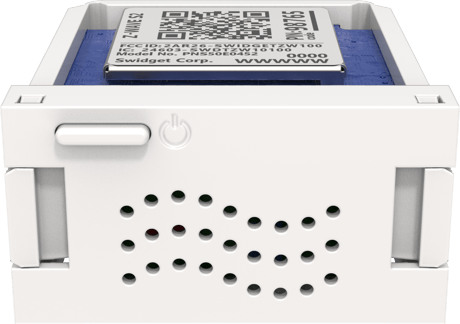
The Swidget Z-Wave™ Control + Air Quality Insert allows users to control and monitor a Swidget Device, and monitors Volatile Organic Compounds (VOCs), temperature, and humidity to provide an Air Quality Index (AQI). The Swidget 15A Outlet offers unique smart features such as advanced automation, energy management capabilities, and external device and appliance regulation capabilities.


1 - Power 1 High Entry Level
Used to set the power value for Power 1 (the controlled load) that indicates entry into a Power 1 High state. NOTE: Under normal circumstances, this value should be set higher than the Power 1 Low threshold values and greater-than or equal to Power 1 High Exit Level.Size: 2 bytes
Default: 2400
Minimum: 0
Maximum: 2400
Possible values
| From | To | Desription |
|---|---|---|
| 0 | 2400 | Watts |
2 - Power 1 Low Entry Level
Used to set the power value for Power 1 (the controlled load) that indicates entry into a Power 1 Low power state. NOTE: Under normal circumstances, this value should be set lower than the Power 1 High threshold values and less-than or equal to the Power 1 Low Exit Level.Size: 2 bytes
Default: 0
Minimum: 0
Maximum: 2400
Possible values
| From | To | Desription |
|---|---|---|
| 0 | 2400 | Watts |
3 - Power 1 High Exit Level
Refer to documentationSize: 2 bytes
Default: 2400
Minimum: 0
Maximum: 2400
Possible values
| From | To | Desription |
|---|---|---|
| 0 | 0 | 0 |
4 - Power 1 Low Exit Level
Used to set the power value for Power 1 (the controlled load) that indicates exit from a Power 1 Low power state. NOTE: Under normal circumstances, this value should be set lower than Power 1 High threshold values and greater-than or equal to Power 1 Low Entry Level.Size: 2 bytes
Default: 0
Minimum: 0
Maximum: 2400
Possible values
| From | To | Desription |
|---|---|---|
| 0 | 2400 | Watts |
5 - Power 1 High Delay
Refer to documentationSize: 2 bytes
Default: 0
Minimum: 0
Maximum: 65535
Possible values
| From | To | Desription |
|---|---|---|
| 0 | 65535 | Seconds |
6 - Power 1 Low Delay
Used to set the time duration that Power 1 Low state change power level conditions must exist before Power 1 Low state entry and/or exit is registered, and the associated actions are executed. See the "Power 1 Low Actions" configuration parameter settings for how the delay can be applied.Size: 2 bytes
Default: 0
Minimum: 0
Maximum: 65535
Possible values
| From | To | Desription |
|---|---|---|
| 0 | 65535 | Seconds |
7 - Power 1 Periodic Report
Used to set the time in seconds between sending Power 1 accumulated kWh METER REPORTs to the Lifeline.Size: 2 bytes
Default: 3600
Minimum: 0
Maximum: 65535
Possible values
| From | To | Desription |
|---|---|---|
| 0 | 0 | Periodic reporting disabled |
| 1 | 29 | Invalid setting (will be set to 30 seconds) |
| 30 | 65535 | Report interval in seconds (minimum 30) |
8 - Power 1 Change Report
Used to set the power in Watts that a reported reading of Power 1 must change by since the last reported value before a new instantaneous Watts METER REPORT is sent to the Lifeline. Note that devices will not exceed recommended report frequency regardless of the rate of power reading changes. If the power is changing rapidly, the device will wait for it to stabilize before reporting the change.Size: 2 bytes
Default: 10
Minimum: 0
Maximum: 2400
Possible values
| From | To | Desription |
|---|---|---|
| 0 | 0 | Change reporting disabled |
| 1 | 9 | Invalid setting (will be set to 10 Watts) |
| 10 | 2400 | Report change threshold in Watts (minimum 10) |
9 - Power 1 Renotification Delay
Used to set the time in seconds between sending repeated Power 1 instantaneous Watts METER REPORTs to the Lifeline while in a Power 1 Low or High state. This can be used to increase report frequency when Power 1 readings are outside of the desired range(s).Size: 2 bytes
Default: 0
Minimum: 0
Maximum: 65535
Possible values
| From | To | Desription |
|---|---|---|
| 0 | 0 | Renotification disabled |
| 1 | 65535 | Renotification interval in seconds |
10 - Power 1 High Entry SET Value
BASIC SET value sent to associated nodes on entry into Power 1 High state.Size: 1 byte
Default: 255
Minimum: 0
Maximum: 255
Possible values
| From | To | Desription |
|---|---|---|
| 0 | 99 | BASIC SET Level 0-99 |
| 100 | 254 | Interpreted as 255 (ON) |
| 255 | 255 | BASIC SET Level 255 (ON) |
11 - Power 1 High Exit SET Value
BASIC SET value sent to associated nodes on exit from Power 1 High state.Size: 1 byte
Default: 0
Minimum: 0
Maximum: 255
Possible values
| From | To | Desription |
|---|---|---|
| 0 | 0 | BASIC SET Level 0 (OFF) |
| 1 | 99 | BASIC SET Level 1-99 |
| 100 | 254 | Interpreted as 255 (ON) |
| 255 | 255 | BASIC SET Level 255 (ON) |
12 - Power 1 Low Entry SET Value
BASIC SET value sent to associated nodes on entry into Power 1 Low state.Size: 1 byte
Default: 255
Minimum: 0
Maximum: 255
Possible values
| From | To | Desription |
|---|---|---|
| 0 | 99 | BASIC SET Level 0-99 |
| 100 | 254 | Interpreted as 255 (ON) |
| 255 | 255 | BASIC SET Level 255 (ON) |
13 - Power 1 Low Exit SET Value
BASIC SET value sent to associated nodes on exit from Power 1 Low state.Size: 1 byte
Default: 0
Minimum: 0
Maximum: 255
Possible values
| From | To | Desription |
|---|---|---|
| 0 | 0 | BASIC SET Level 0 (OFF) |
| 1 | 99 | BASIC SET Level 1-99 |
| 100 | 254 | Interpreted as 255 (ON) |
| 255 | 255 | BASIC SET Level 255 (ON) |
14 - Power 1 High Actions
Enable/disable various high-power reporting and activation capabilities.Size: 2 bytes
Default: 99
Minimum: 0
Maximum: 127
Possible values
| From | To | Desription |
|---|---|---|
| 1 | 1 | CONTROL ASSOCIATIONS ON ENTRY (Bit 0) |
| 2 | 2 | CONTROL ASSOCIATIONS ON EXIT (Bit 1) |
| 4 | 4 | CONTROL HOST ON ENTRY (Bit 2) |
| 8 | 8 | CONTROL HOST ON EXIT (Bit 3) |
| 16 | 16 | REPORT TRANSITIONS (Bit 4) |
| 32 | 32 | APPLY ENTRY DELAY (Bit 5) |
| 64 | 64 | APPLY EXIT DELAY (Bit 6) |
15 - Power 1 Low Actions
Enable/disable various low-power related reporting and activation capabilities.Size: 2 bytes
Default: 99
Minimum: 0
Maximum: 127
Possible values
| From | To | Desription |
|---|---|---|
| 1 | 1 | CONTROL ASSOCIATIONS ON ENTRY (Bit 0) |
| 2 | 2 | CONTROL ASSOCIATIONS ON EXIT (Bit 1) |
| 4 | 4 | CONTROL HOST ON ENTRY (Bit 2) |
| 8 | 8 | CONTROL HOST ON EXIT (Bit 3) |
| 16 | 16 | REPORT TRANSITIONS (Bit 4) |
| 32 | 32 | APPLY ENTRY DELAY (Bit 5) |
| 64 | 64 | APPLY EXIT DELAY (Bit 6) |
24 - Power 2 High Entry Level
Used to set the power value for Power 2 that indicates entry into a Power 2 High state. NOTE: Under normal circumstances, this value should be set higher than the Power 2 Low threshold values and greater-than or equal to Power 2 High Exit Level.Size: 2 bytes
Default: 2400
Minimum: 0
Maximum: 2400
Possible values
| From | To | Desription |
|---|---|---|
| 0 | 2411 | Watts |
25 - Power 2 Low Entry Level
Used to set the power value for Power 2 that indicates entry into a Power 2 Low power state. NOTE: Under normal circumstances, this value should be set lower than the Power 2 High threshold values and less-than or equal to the Power 2 Low Exit Level.Size: 2 bytes
Default: 0
Minimum: 0
Maximum: 2400
Possible values
| From | To | Desription |
|---|---|---|
| 0 | 2400 | Watts |
26 - Power 2 High Exit Level
Used to set the power value for Power 2 that indicates exit from a Power 2 High state. NOTE: Under normal circumstances, this value should be set higher than Power 2 Low threshold values and less-than or equal to Power 2 High Entry Level.Size: 2 bytes
Default: 2400
Minimum: 0
Maximum: 2400
Possible values
| From | To | Desription |
|---|---|---|
| 0 | 2400 | Watts |
27 - Power 2 Low Exit Level
Used to set the power value for Power 2 that indicates exit from a Power 2 Low state. NOTE: Under normal circumstances, this value should be set lower than Power 2 High threshold values and greater-than or equal to Power 2 Low Entry Level.Size: 2 bytes
Default: 0
Minimum: 0
Maximum: 2400
Possible values
| From | To | Desription |
|---|---|---|
| 0 | 2400 | Watts |
28 - Power 2 High Delay
Used to set the time duration that Power 2 High state change power level conditions must exist before Power 2 High state entry and/or exit is registered, and the associated actions are executed. See the “Power 2 High Actions” configuration parameter settings for how the delay can be applied.Size: 2 bytes
Default: 0
Minimum: 0
Maximum: 65535
Possible values
| From | To | Desription |
|---|---|---|
| 0 | 65535 | Seconds |
29 - Power 2 Low Delay
Used to set the time duration that Power 2 Low state change power level conditions must exist before Power 2 Low state entry and/or exit is registered, and the associated actions are executed. See the "Power 2 Low Actions" configuration parameter settings for how the delay can be applied.Size: 2 bytes
Default: 0
Minimum: 0
Maximum: 65535
Possible values
| From | To | Desription |
|---|---|---|
| 0 | 65535 | Seconds |
30 - Power 2 Periodic Report
Used to set the time in seconds between sending Power 2 accumulated kWh METER REPORTs to the Lifeline. NOTE: Power 2 Meter Reports are only delivered to Lifeline associations created with a Multi-Channel Association.Size: 2 bytes
Default: 3600
Minimum: 0
Maximum: 65535
Possible values
| From | To | Desription |
|---|---|---|
| 0 | 0 | Periodic reporting disabled |
| 1 | 29 | Invalid setting (will be set to 30 seconds) |
| 30 | 65535 | Report interval in seconds (minimum 30) |
31 - Power 2 Change Report
Used to set the power in Watts that a reported reading of Power 2 must change by since the last reported value before a new instantaneous Watts METER REPORT is sent to the Lifeline. Note that devices will not exceed recommended report frequency regardless of the rate of power reading changes. If the power is changing rapidly, the device will wait for it to stabilize before reporting the change. NOTE: Power 2 Meter Reports are only delivered to Lifeline associations created with a Multi-Channel Association.Size: 2 bytes
Default: 10
Minimum: 0
Maximum: 2400
Possible values
| From | To | Desription |
|---|---|---|
| 0 | 0 | Change reporting disabled |
| 1 | 9 | Invalid setting (will be set to 10 Watts) |
| 10 | 2400 | Report change threshold in Watts (minimum 10) |
32 - Power 2 Renotification Delay
Used to set the time in seconds between sending repeated Power 2 instantaneous Watts METER REPORTs to the Lifeline while in a Power 2 Low or High state. This can be used to increase report frequency when Power 2 readings are outside of the desired range(s). NOTE: Power 2 Meter Reports are only delivered to Lifeline associations created with a Multi-Channel Association.Size: 2 bytes
Default: 0
Minimum: 0
Maximum: 65535
Possible values
| From | To | Desription |
|---|---|---|
| 0 | 0 | Renotification disabled |
| 1 | 65535 | Renotification interval in seconds |
33 - Power 2 High Entry SET Value
BASIC SET value sent to associated nodes on entry into Power 2 High state.Size: 1 byte
Default: 255
Minimum: 0
Maximum: 255
Possible values
| From | To | Desription |
|---|---|---|
| 0 | 99 | BASIC SET Level 0-99 |
| 100 | 254 | Interpreted as 255 (ON) |
| 255 | 255 | BASIC SET Level 255 (ON) |
34 - Power 2 High Exit SET Value
BASIC SET value sent to associated nodes on exit from Power 2 High state.Size: 1 byte
Default: 0
Minimum: 0
Maximum: 255
Possible values
| From | To | Desription |
|---|---|---|
| 0 | 0 | BASIC SET Level 0 (OFF) |
| 1 | 99 | BASIC SET Level 1-99 |
| 100 | 254 | Interpreted as 255 (ON) |
| 255 | 255 | BASIC SET Level 255 (ON) |
35 - Power 2 Low Entry SET Value
BASIC SET value sent to associated nodes on entry into Power 2 Low state.Size: 1 byte
Default: 255
Minimum: 0
Maximum: 255
Possible values
| From | To | Desription |
|---|---|---|
| 0 | 99 | BASIC SET Level 0-99 |
| 100 | 254 | Interpreted as 255 (ON) |
| 255 | 255 | BASIC SET Level 255 (ON) |
36 - Power 2 Low Exit SET Value
BASIC SET value sent to associated nodes on exit from Power 2 Low state.Size: 1 byte
Default: 0
Minimum: 0
Maximum: 255
Possible values
| From | To | Desription |
|---|---|---|
| 0 | 0 | BASIC SET Level 0 (OFF) |
| 1 | 99 | BASIC SET Level 1-99 |
| 100 | 254 | Interpreted as 255 (ON) |
| 255 | 255 | BASIC SET Level 255 (ON) |
37 - Power 2 High Actions
Enable/disable various high-power reporting and activation capabilities.Size: 2 bytes
Default: 99
Minimum: 0
Maximum: 127
Possible values
| From | To | Desription |
|---|---|---|
| 1 | 1 | CONTROL ASSOCIATIONS ON ENTRY (Bit 0) |
| 2 | 2 | CONTROL ASSOCIATIONS ON EXIT (Bit 1) |
| 4 | 4 | CONTROL HOST ON ENTRY (Bit 2) |
| 8 | 8 | CONTROL HOST ON EXIT (Bit 3) |
| 16 | 16 | REPORT TRANSITIONS (Bit 4) |
| 32 | 32 | APPLY ENTRY DELAY (Bit 5) |
| 64 | 64 | APPLY EXIT DELAY (Bit 6) |
38 - Power 2 Low Actions
Enable/disable various low-power related reporting and activation capabilities.Size: 2 bytes
Default: 99
Minimum: 0
Maximum: 127
Possible values
| From | To | Desription |
|---|---|---|
| 1 | 1 | CONTROL ASSOCIATIONS ON ENTRY (Bit 0) |
| 2 | 2 | CONTROL ASSOCIATIONS ON EXIT (Bit 1) |
| 4 | 4 | CONTROL HOST ON ENTRY (Bit 2) |
| 8 | 8 | CONTROL HOST ON EXIT (Bit 3) |
| 16 | 16 | REPORT TRANSITIONS (Bit 4) |
| 32 | 32 | APPLY ENTRY DELAY (Bit 5) |
| 64 | 64 | APPLY EXIT DELAY (Bit 6) |
64 - Air Quality Level 1 Index
Used to set the index value representing the upper limit for the "Clean" air state. Above this level, the air state is set to "Slightly Polluted"Size: 2 bytes
Default: 100
Minimum: 0
Maximum: 500
Possible values
| From | To | Desription |
|---|---|---|
| 0 | 500 | 0 == cleanest, 500 == most polluted |
65 - Air Quality Level 2 Index
Used to set the index value representing the upper limit for the "Slightly Polluted" air state. Above this level, the air state is set to "Moderately Polluted"Size: 2 bytes
Default: 175
Minimum: 0
Maximum: 500
Possible values
| From | To | Desription |
|---|---|---|
| 0 | 500 | 0 == cleanest, 500 == most polluted |
66 - Air Quality Level 3 Index
Used to set the index value representing the upper limit for the "Moderately Polluted" air state. Above this level, the air state is set to "Extremely Polluted"Size: 2 bytes
Default: 250
Minimum: 0
Maximum: 500
Possible values
| From | To | Desription |
|---|---|---|
| 0 | 500 | 0 == cleanest, 500 == most polluted |
67 - Air Quality Alert Level
Used to set the air quality level that will trigger Air Quality Alert State actionsSize: 1 byte
Default: 2
Minimum: 1
Maximum: 3
Possible values
| From | To | Desription |
|---|---|---|
| 1 | 1 | Slightly Polluted |
| 2 | 2 | Moderately Polluted |
| 3 | 3 | Extremely Polluted |
68 - Air Quality Alert Delay
Delay (seconds) after detection of a level change before acting on change of air quality stateSize: 2 bytes
Default: 0
Minimum: 0
Maximum: 65535
Possible values
| From | To | Desription |
|---|---|---|
| 0 | 65535 | Seconds |
69 - Air Quality Renotification Delay
Used to set the time in seconds between optionally resending NOTIFICATION REPORT (Home Health: VOC Level Status Event) messages to the Lifeline while in an "Air Quality Alert" state.Size: 2 bytes
Default: 300
Minimum: 0
Maximum: 65535
Possible values
| From | To | Desription |
|---|---|---|
| 0 | 0 | No renotifications |
| 1 | 29 | Invalid setting (will be set to 30 seconds) |
| 30 | 65535 | Renotification interval in seconds (minimum 30) |
70 - Air Quality VOC Periodic Report
Used to set the time in seconds between sending a periodic "Volatile Organic Compound level” MULTILEVEL SENSOR REPORT to the LifelineSize: 2 bytes
Default: 3600
Minimum: 0
Maximum: 65535
Possible values
| From | To | Desription |
|---|---|---|
| 0 | 0 | No VOC reporting active |
| 1 | 59 | Invalid setting (will be set to 60 seconds) |
| 60 | 65535 | Report interval in seconds (minimum 60) |
72 - Air Quality Alert Entry SET Value
BASIC SET value sent to associated nodes on entry into air quality alert stateSize: 1 byte
Default: 255
Minimum: 0
Maximum: 255
Possible values
| From | To | Desription |
|---|---|---|
| 0 | 99 | BASIC SET Level 0-99 |
| 255 | 255 | BASIC SET Level 255 (ON) |
73 - Air Quality Alert Exit SET Value
BASIC SET value sent to associated nodes on exit from air quality alert stateSize: 1 byte
Default: 0
Minimum: 0
Maximum: 255
Possible values
| From | To | Desription |
|---|---|---|
| 0 | 99 | BASIC SET Level 0-99 |
| 255 | 255 | BASIC SET Level 255 (ON) |
74 - Air Quality Actions
Enable/disable various Indoor Air Quality sensor related capabilities.Size: 2 bytes
Default: 19
Minimum: 0
Maximum: 31
Possible values
| From | To | Desription |
|---|---|---|
| 1 | 1 | CONTROL ASSOCIATIONS ON ENTRY (Air Quality Alert) (Bit 0) |
| 2 | 2 | CONTROL ASSOCIATIONS ON EXIT (Air Quality Alert) (Bit 1) |
| 4 | 4 | CONTROL HOST ON ENTRY (Air Quality Alert) (Bit 2) |
| 8 | 8 | CONTROL HOST ON EXIT (Air Quality Alert) (Bit 3) |
| 16 | 16 | RENOTIFY (VOC Level Status Event) (Bit 4) |
152 - System Status
Used to provide status information for system troubleshooting. [READ ONLY] [ADVANCED]Size: 4 bytes
Default: 0
Minimum: 0
Maximum: 4294967295
Possible values
| From | To | Desription |
|---|---|---|
| 0 | 0 | 0 |
153 - System LED Brightness
Used to set the power output to the system LED to control on brightness level.Size: 1 byte
Default: 100
Minimum: 0
Maximum: 100
Possible values
| From | To | Desription |
|---|---|---|
| 0 | 100 | percent |
154 - System Options
Configure various system wide features and capabilities.Size: 2 bytes
Default: 0
Minimum: 0
Maximum: 1
Possible values
| From | To | Desription |
|---|---|---|
| 0 | 0 | LED Invert (Bit 0=0): LED follows state of host switch, on when host is on. |
| 1 | 1 | LED Invert (Bit 0=1): LED is inverse of state of host switch, off when host is on. |
Follow network ADD steps for your Z-Wave controller / hub. Lightly press Insert push button and hold for 5-10 seconds until the LED illuminates solid blue, then release. LED will flash blue to indicate ADD mode is enabled. No manual or external Z-Wave operations are possible during this activity. Insert will remain in ADD mode for up to 30 seconds. If successful, LED will be solid blue for 5 seconds then return to the normal operational state. IF FAILED to connect after 30 seconds, the red LED will flash for 3 seconds, indicating no or failed network ADD. If necessary, consult your Z-Wave controller/hub manual and retry.
Follow network REMOVE steps for your Z-Wave controller / hub. Lightly press Insert push button and hold for 5-10 seconds then release. LED will flash blue to indicate REMOVE mode is enabled. No manual or external Z-Wave operations are possible during this activity. Insert will remain in REMOVE mode for up to 30 seconds. If successful, LED will be solid blue for 5 seconds then return to the normal operational state. If FAILED to connect after 60 seconds, red LED will flash indicating no or failed network REMOVE. If necessary, consult your Z-Wave controller / hub manual and retry.
Should only be used when the original controller is inoperable or has been replaced. Lightly press Insert push button and hold for 10-15 seconds until the LED turns SOLID RED, and then release.
Use the Z-Wave controller / hub app or interface to scan the QR code located on the security card or directly on the insert, or manually enter the 5 digit PIN or insert''s full DSK (Device Specific Key) as required.
| Type | Value(s) |
|---|
| Group | Type |
|---|---|
| Heat Alarm |
|
| Home Health | VOC level status: Volatile Organic Compound level |
| Sensor type |
|---|
| Air Temperature |
| Humidity |
| Volatile Organic Compound Level |