Nice
RGBW-Control
FGRGBW-442
Multilevel Switch - Color Tunable Multilevel
HW: 2 FW: 5.01:05.01:01.00
ZM5101
6.81.03
0x010F (271)
0x0902 (2306)
0x1000 (4096)
ZC10-23127125
2023-12-01 14:59:57.665068
N/A
Enhanced 232 Slave
Always On Slave
RGBW-Control is a universal, Z-Wave Plus™ compatible RGB/RGBW controller. The device uses PWM output signal, allowing it to control LED, RGB, RGBW strips, halogen lights and other resistive loads
RGBW-Control is a universal, Z-Wave Plus™ compatible RGB/RGBW controller. The device uses PWM output signal, allowing it to control LED, RGB, RGBW strips, halogen lights and other resistive loads. It can also measure active power and energy consumed by the load. Controlled devices may be powered by 12 or 24V DC. Inputs support momentary/toggle switches and 0-10V analog sensors, like temperature sensors, humidity sensors, light sensors etc.
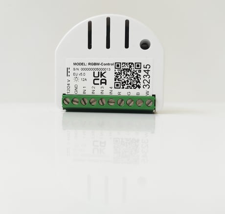
Product Image


1 - Remember device status before the power failure
This parameter determines how the device will react in the event of power supply failure (e.g. power outage or taking out from the electrical outlet). After the power supply is back on, the device can be restored to previous state or remain switched off. The sequence is not remembered after the power returns. After power failure, the last color set before the sequence will be restored.Size: 1 byte
Default: 0
Minimum: 0
Maximum: 1
Possible values
| From | To | Desription |
|---|---|---|
| 0 | 0 | device remains switched off |
| 1 | 1 | device restores the state from before the power failure |
20 - Input 1 - operating mode
This parameter allows to choose mode of 1st input (IN1). Change it depending on connected device.Size: 1 byte
Default: 2
Minimum: 0
Maximum: 4
Possible values
| From | To | Desription |
|---|---|---|
| 0 | 0 | Analog input without internal pull-up (Sensor Multilevel) |
| 1 | 1 | Analog input with internal pull-up (Sensor Multilevel) |
| 2 | 2 | Momentary switch (Central Scene) |
| 3 | 3 | Toggle switch: switch state on every input change (Central Scene) |
| 4 | 4 | Toggle switch: contact closed – ON, contact opened – OFF (Central Scene) |
21 - Input 2 - operating mode
This parameter allows to choose mode of 2nd input (IN2). Change it depending on connected device.Size: 1 byte
Default: 2
Minimum: 0
Maximum: 4
Possible values
| From | To | Desription |
|---|---|---|
| 0 | 0 | Analog input without internal pull-up (Sensor Multilevel) |
| 1 | 1 | Analog input with internal pull-up (Sensor Multilevel) |
| 2 | 2 | Momentary switch (Central Scene) |
| 3 | 3 | Toggle switch: switch state on every input change (Central Scene) |
| 4 | 4 | Toggle switch: contact closed – ON, contact opened – OFF (Central Scene) |
22 - Input 3 - operating mode
This parameter allows to choose mode of 3rd input (IN3). Change it depending on connected device.Size: 1 byte
Default: 2
Minimum: 0
Maximum: 4
Possible values
| From | To | Desription |
|---|---|---|
| 0 | 0 | Analog input without internal pull-up (Sensor Multilevel) |
| 1 | 1 | Analog input with internal pull-up (Sensor Multilevel) |
| 2 | 2 | Momentary switch (Central Scene) |
| 3 | 3 | Toggle switch: switch state on every input change (Central Scene) |
| 4 | 4 | Toggle switch: contact closed – ON, contact opened – OFF (Central Scene) |
23 - Input 4 - operating mode
This parameter allows to choose mode of 4th input (IN4). Change it depending on connected device.Size: 1 byte
Default: 2
Minimum: 0
Maximum: 4
Possible values
| From | To | Desription |
|---|---|---|
| 0 | 0 | Analog input without internal pull-up (Sensor Multilevel) |
| 1 | 1 | Analog input with internal pull-up (Sensor Multilevel) |
| 2 | 2 | Momentary switch (Central Scene) |
| 3 | 3 | Toggle switch: switch state on every input change (Central Scene) |
| 4 | 4 | Toggle switch: contact closed – ON, contact opened – OFF (Central Scene) |
30 - Alarm configuration - 1st slot
This parameter determines to which alarm frames and how the device should react. The parameters consist of 4 bytes, three most significant bytes are set according to the official Z-Wave protocol specification. X – channels summarized: 1/2/3/4 channel are equal to values 1/2/4/8. Y – sequence number: 1-10 (parameter 157).Size: 4 bytes
Default: 0
Minimum: 0
Maximum: 2147483647
Possible values
| From | To | Desription |
|---|---|---|
| 0 | 255 | [LSB] – Action |
| 256 | 65535 | Event/State Parameters |
| 65536 | 16777215 | Notification Status |
| 16777216 | 2147483647 | [MSB] – Notification Type |
31 - Alarm configuration - 2nd slot
This parameter determines to which alarm frames and how the device should react. The parameters consist of 4 bytes, three most significant bytes are set according to the official Z-Wave protocol specification. X – channels summarized: 1/2/3/4 channel are equal to values 1/2/4/8. Y – sequence number: 1-10 (parameter 157).Size: 4 bytes
Default: 100597760
Minimum: 0
Maximum: 2147483647
Possible values
| From | To | Desription |
|---|---|---|
| 0 | 255 | [LSB] – Action |
| 256 | 65535 | Event/State Parameters |
| 65536 | 16777215 | Notification Status |
| 16777216 | 2147483647 | [MSB] – Notification Type |
32 - Alarm configuration - 3rd slot
This parameter determines to which alarm frames and how the device should react. The parameters consist of 4 bytes, three most significant bytes are set according to the official Z-Wave protocol specification. X – channels summarized: 1/2/3/4 channel are equal to values 1/2/4/8. Y – sequence number: 1-10 (parameter 157).Size: 4 bytes
Default: 33488896
Minimum: 0
Maximum: 2147483647
Possible values
| From | To | Desription |
|---|---|---|
| 0 | 255 | [LSB] – Action |
| 256 | 65535 | Event/State Parameters |
| 65536 | 16777215 | Notification Status |
| 16777216 | 2147483647 | [MSB] – Notification Type |
33 - Alarm configuration - 4th slot
This parameter determines to which alarm frames and how the device should react. The parameters consist of 4 bytes, three most significant bytes are set according to the official Z-Wave protocol specification. X – channels summarized: 1/2/3/4 channel are equal to values 1/2/4/8. Y – sequence number: 1-10 (parameter 157).Size: 4 bytes
Default: 50266112
Minimum: 0
Maximum: 2147483647
Possible values
| From | To | Desription |
|---|---|---|
| 0 | 255 | [LSB] – Action |
| 256 | 65535 | Event/State Parameters |
| 65536 | 16777215 | Notification Status |
| 16777216 | 2147483647 | [MSB] – Notification Type |
34 - Alarm configuration - 5th slot
This parameter determines to which alarm frames and how the device should react. The parameters consist of 4 bytes, three most significant bytes are set according to the official Z-Wave protocol specification. X – channels summarized: 1/2/3/4 channel are equal to values 1/2/4/8. Y – sequence number: 1-10 (parameter 157).Size: 4 bytes
Default: 83820544
Minimum: 0
Maximum: 2147483647
Possible values
| From | To | Desription |
|---|---|---|
| 0 | 255 | [LSB] – Action |
| 256 | 65535 | Event/State Parameters |
| 65536 | 16777215 | Notification Status |
| 16777216 | 2147483647 | [MSB] – Notification Type |
35 - Duration of alarm signalization
This parameter determines the duration of alarm signaling (flashing mode and/or alarm sequence).Size: 2 bytes
Default: 0
Minimum: 0
Maximum: 32400
Possible values
| From | To | Desription |
|---|---|---|
| 0 | 0 | infinite signalization |
| 1 | 32400 | (1s-9h, 1s step) |
40 - Input 1 - sent scenes
This parameter defines which actions result in sending scene ID and attribute assigned to them. Parameter is relevant only if parameter 20 is set to 2, 3 or 4. Actions can be summed up, e.g. 1+2+4+8=15 and entered as a value for the parameter.Size: 1 byte
Default: 15
Minimum: 0
Maximum: 15
Possible values
| From | To | Desription |
|---|---|---|
| 0 | 0 | No scenes sent |
| 1 | 1 | Key pressed 1 time |
| 2 | 2 | Key pressed 2 times |
| 4 | 4 | Key pressed 3 times |
| 8 | 8 | Key held down and key released |
| 15 | 15 | All scenes sent |
41 - Input 2 - sent scenes
This parameter defines which actions result in sending scene ID and attribute assigned to them. Parameter is relevant only if parameter 21 is set to 2, 3 or 4. Actions can be summed up, e.g. 1+2+4+8=15 and entered as a value for the parameter.Size: 1 byte
Default: 15
Minimum: 0
Maximum: 15
Possible values
| From | To | Desription |
|---|---|---|
| 0 | 0 | No scenes sent |
| 1 | 1 | Key pressed 1 time |
| 2 | 2 | Key pressed 2 times |
| 4 | 4 | Key pressed 3 times |
| 8 | 8 | Key held down and key released |
| 15 | 15 | All scenes sent |
42 - Input 3 - sent scenes
This parameter defines which actions result in sending scene ID and attribute assigned to them. Parameter is relevant only if parameter 22 is set to 2, 3 or 4. Actions can be summed up, e.g. 1+2+4+8=15 and entered as a value for the parameter.Size: 1 byte
Default: 15
Minimum: 0
Maximum: 15
Possible values
| From | To | Desription |
|---|---|---|
| 0 | 0 | No scenes sent |
| 1 | 1 | Key pressed 1 time |
| 2 | 2 | Key pressed 2 times |
| 4 | 4 | Key pressed 3 times |
| 8 | 8 | Key held down and key released |
| 15 | 15 | All scenes sent |
43 - Input 4 - sent scenes
This parameter defines which actions result in sending scene ID and attribute assigned to them. Parameter is relevant only if parameter 23 is set to 2, 3 or 4. Actions can be summed up, e.g. 1+2+4+8=15 and entered as a value for the parameter.Size: 1 byte
Default: 15
Minimum: 0
Maximum: 15
Possible values
| From | To | Desription |
|---|---|---|
| 0 | 0 | No scenes sent |
| 1 | 1 | Key pressed 1 time |
| 2 | 2 | Key pressed 2 times |
| 4 | 4 | Key pressed 3 times |
| 8 | 8 | Key held down and key released |
| 15 | 15 | All scenes sent |
62 - Power reports - periodic
This parameter determines in what time intervals the periodic power reports are sent to the main controller. Periodic reports do not depend of power change (parameter 61).Size: 2 bytes
Default: 3600
Minimum: 0
Maximum: 32400
Possible values
| From | To | Desription |
|---|---|---|
| 0 | 0 | periodic reports are disabled |
| 30 | 32400 | (30 - 32400 s) - report interval |
63 - Analog inputs reports and output change on input change
This parameter defines minimal change (from the last reported) of analog input voltage that results in sending new report and change in the output value. Parameter is relevant only for analog inputs (parameter 20, 21, 22 or 23 set to 0 or 1).Size: 2 bytes
Default: 5
Minimum: 0
Maximum: 100
Possible values
| From | To | Desription |
|---|---|---|
| 0 | 0 | reporting on change disabled |
| 1 | 100 | 0.1 - 10 V, 0.1 V step |
64 - Analog inputs reports - periodic
This parameter defines reporting period of analog inputs value. Periodical reports are independent from changes in value (parameter 63). Parameter is relevant only for analog inputs (parameter 20, 21, 22 or 23 set to 0 or 1).Size: 2 bytes
Default: 0
Minimum: 0
Maximum: 32400
Possible values
| From | To | Desription |
|---|---|---|
| 0 | 0 | periodical reports disabled |
| 30 | 32400 | 30 - 32400 s, 1 s step |
65 - Energy reports - on change
This parameter determines the minimum change in consumed energy that will result in sending new energy report to the main controller. Energy reports are sent no often than every 30 seconds.Size: 2 bytes
Default: 10
Minimum: 0
Maximum: 500
Possible values
| From | To | Desription |
|---|---|---|
| 0 | 0 | reports are disabled |
| 1 | 500 | (0.01 - 5 kWh) - change in energy |
66 - Energy reports - periodic
This parameter determines in what time intervals the periodic energy reports are sent to the main controller. Periodic reports do not depend of energy change (parameter 65)Size: 2 bytes
Default: 3600
Minimum: 0
Maximum: 32400
Possible values
| From | To | Desription |
|---|---|---|
| 0 | 0 | periodic reports are disabled |
| 30 | 32400 | (30 - 32400 s) - report interval |
150 - Inputs - LED colour control mode
This parameter determines how connected switches control LED strips.Size: 1 byte
Default: 0
Minimum: 0
Maximum: 1
Possible values
| From | To | Desription |
|---|---|---|
| 0 | 0 | RGBW mode (every input controls output with the same number, IN1‑OUT1, IN2‑OUT2, IN3‑OUT3, IN4‑OUT4) |
| 1 | 1 | HSB and White mode (inputs works in HSB color model, IN1‑H (Hue), IN2‑S (Saturation), IN3‑B (Brightness), IN4‑White (OUT4) |
151 - Local control - transition time
This parameter determines time of smooth transition between 0% and 100% when controlling with connected switches.Size: 2 bytes
Default: 3
Minimum: 0
Maximum: 254
Possible values
| From | To | Desription |
|---|---|---|
| 0 | 0 | instantly |
| 1 | 127 | 1 s - 127 s, 1 s step |
| 128 | 254 | 1 min - 127 min, 1 min step |
152 - Remote control - transition time
This parameter determines time needed to change the state between current and target values when controlling via Z-Wave network.Size: 2 bytes
Default: 0
Minimum: 0
Maximum: 254
Possible values
| From | To | Desription |
|---|---|---|
| 0 | 0 | instantly |
| 1 | 127 | 1 s - 127 s, 1 s step |
| 128 | 254 | 1 min - 127 min, 1 min step |
154 - ON frame value for single click
This parameter defines value sent to devices in association groups. The parameters consist of 4 bytes, each byte reserved for separate channel, from least significant (IN1) to most significant (IN4). Applicable for Basic Set and Switch Multilevel Set commands.Size: 4 bytes
Default: 2147483647
Minimum: 0
Maximum: 2147483647
Possible values
| From | To | Desription |
|---|---|---|
| 0 | 99 | value for every byte (MSB to LSB) |
| 255 | 255 | value for every byte (MSB to LSB) |
155 - OFF frame value for single click
This parameter defines value sent to devices in association groups. The parameters consist of 4 bytes, each byte reserved for separate channel, from least significant (IN1) to most significant (IN4). Applicable for Basic Set and Switch Multilevel Set commands.Size: 4 bytes
Default: 0
Minimum: 0
Maximum: 2147483647
Possible values
| From | To | Desription |
|---|---|---|
| 0 | 99 | value for every byte (MSB to LSB) |
| 255 | 255 | value for every byte (MSB to LSB) |
156 - ON frame value for double click
This parameter defines value sent to devices in association groups. The parameters consist of 4 bytes, each byte reserved for separate channel, from least significant (IN1) to most significant (IN4). Applicable for Basic Set and Switch Multilevel Set commands.Size: 4 bytes
Default: 1667457891
Minimum: 0
Maximum: 2147483647
Possible values
| From | To | Desription |
|---|---|---|
| 0 | 99 | value for every byte (MSB to LSB) |
| 255 | 255 | value for every byte (MSB to LSB) |
157 - Start programmed sequence
Setting this parameter will start programmed sequence with selected number. User can define own sequences via controller. While the sequence is active, the menu is unavailable.Size: 1 byte
Default: 0
Minimum: 0
Maximum: 10
Possible values
| From | To | Desription |
|---|---|---|
| 0 | 0 | sequence inactive |
| 1 | 5 | user-defined sequence |
| 6 | 6 | Fireplace sequence |
| 7 | 7 | Storm sequence |
| 8 | 8 | Rainbow sequence |
| 9 | 9 | Aurora sequence |
| 10 | 10 | Police (red-white-blue) sequence |
4.1 - Adding manually To add the device to the Z-Wave network manually: 1. Power the device. 2. Set the main controller in (Security/non-Security Mode) add mode (see the controller’s manual). 3. Quickly, three times click the service button. 4. If you are adding in Security S2 Authenticated, input the underlined part of the DSK (label on the box). 5. LED will start blinking yellow, wait for the adding process to end. 6. Adding result will be confirmed by the Z-Wave controller’s message and the LED: • Green – successful (non-secure, S0, S2 Unauthenticated), • Magenta – successful (Security S2 Authenticated), • Red – not successful.
To remove the device from the Z-Wave network: 1. Power the device. 2. Set the main controller into remove mode (see the controller’s manual). 3. Quickly, three times click the service button. 4. LED will start blinking yellow, wait for the removing process to end. 5. Successful removing will be confirmed by the Z-Wave controller’s message and red LED colour.
1. Press and hold the service button to enter the menu. 2. Release service button when the device glows yellow. 3. Quickly click the service button to confirm. 4. After few seconds the device will be restarted, which is signalled with the red colour.
Full DSK code is present only on the box, make sure to keep it or copy the code. If you are adding in Security S2 Authenticated, input the underlined part of the DSK (label on the box). Enter the full DSK string code to your controller. If your controller is capable of QR scanning, scan the QR code placed on the label on the box.
| Type | Value(s) |
|---|
| Group | Type |
|---|---|
| Power Management | Over-current status: Over-current detected |
| System | HW status: System hardware failure (manufacturer proprietary failure code provided) |
| Sensor type |
|---|
| Voltage |
| Meter type |
|---|
| Electric Meter Consumption |