FIBAR GROUP S.A.
Roller Shutter 4
FGR-224
Window Covering DT
HW: 04 FW: 08.01
EFR32ZG23B
7.18.8
0x010F (271)
0x0304 (772)
0x1000 (4096)
ZC14-23120375
2023-12-14 21:00:30
N/A
Enhanced End Node 232
Always On End Node
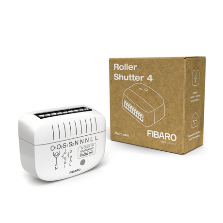
FIBARO ROLLER SHUTTER 4 is a device designed to control roller blinds, awnings, venetian blinds, curtains and pergolas.


20 - Switch type
This parameter determines with which switches types and in which mode the S1 and S2 inputs operate.Size: 1 byte
Default: 0
Minimum: 0
Maximum: 5
Possible values
| From | To | Desription |
|---|---|---|
| 0 | 0 | Monostable switches - click to move |
| 1 | 1 | Monostable switches - hold to move |
| 2 | 2 | Single monostable switch |
| 3 | 3 | Bistable switches |
| 4 | 4 | Single bistable switch |
| 5 | 5 | Three-state switch |
24 - Buttons orientation
This parameter allows reversing the operation of the buttons.Size: 1 byte
Default: 0
Minimum: 0
Maximum: 1
Possible values
| From | To | Desription |
|---|---|---|
| 0 | 0 | default (1st button UP, 2nd button DOWN) |
| 1 | 1 | reversed (1st button DOWN, 2nd button UP) |
25 - Outputs orientation
This parameter allows reversing the operation of 01 and O2 without changing the wiring (e.g. in case of invalid motor connection).Size: 1 byte
Default: 0
Minimum: 0
Maximum: 1
Possible values
| From | To | Desription |
|---|---|---|
| 0 | 0 | default (01 - UP, O2 - DOWN) |
| 1 | 1 | reversed (01 - DOWN, O2 – UP) |
40 - First button - scenes sent
This parameter determines which actions result in sending scene IDs assigned to them. Values can be combined (e.g. 1+2=3 means that scenes for single and double click are sent). Enabling scenes for triple click disables entering the device in learn mode by triple clicking.Size: 1 byte
Default: 15
Minimum: 0
Maximum: 15
Possible values
| From | To | Desription |
|---|---|---|
| 0 | 0 | No scene active |
| 1 | 1 | Key pressed 1 time |
| 2 | 2 | Key pressed 2 times |
| 4 | 4 | Key pressed 3 times |
| 8 | 8 | Key hold down and key released |
41 - Second button - scenes sent
This parameter determines which actions result in sending scene IDs assigned to them. Values can be combined (e.g. 1+2=3 means that scenes for single and double click are sent). Enabling scenes for triple click disables entering the device in learn mode by triple clicking.Size: 1 byte
Default: 15
Minimum: 0
Maximum: 15
Possible values
| From | To | Desription |
|---|---|---|
| 0 | 0 | No scene active |
| 1 | 1 | Key pressed 1 time |
| 2 | 2 | Key pressed 2 times |
| 4 | 4 | Key pressed 3 times |
| 8 | 8 | Key hold down and key released |
150 - Calibration
To start automatic calibration, select the value 3. When the calibration process is successful, the parameter takes the value 1. When automatic calibration fails, the parameter takes the value 2. If the transitions times for the device are changed manually in the parameter (156/157), the parameter 150 will takes the value 4.Size: 1 byte
Default: 0
Minimum: 0
Maximum: 4
Possible values
| From | To | Desription |
|---|---|---|
| 0 | 0 | Device is not calibrated |
| 1 | 1 | Autocalibration successful |
| 2 | 2 | Autocalibration failed |
| 3 | 3 | Calibration process |
| 4 | 4 | Manual calibration |
151 - Operating mode
This parameter allows you to adjust the operation, depending on the connected device. In the case of venetian blinds, the angle of rotation of the slats must also be selected.Size: 1 byte
Default: 0
Minimum: 0
Maximum: 2
Possible values
| From | To | Desription |
|---|---|---|
| 0 | 0 | Roller blind, Awning, Pergola, Curtain |
| 1 | 1 | Venetian blind 90° |
| 2 | 2 | Venetian blind 180° |
152 - Venetian blind - slats full turn time
For Venetian blinds the parameter determines time of full turn cycle of the slats. The parameter is irrelevant for other modes.Size: 2 bytes
Default: 15
Minimum: 0
Maximum: 65535
Possible values
| From | To | Desription |
|---|---|---|
| 0 | 65535 | 0-65535 (0-6553.5s, every 0.1s) - time of turn |
156 - Time of up movement
This parameter determines the time it takes to reach full opening. The value is set automatically during the calibration process. It should be manually set in case of problems with the autocalibration.Size: 2 bytes
Default: 600
Minimum: 0
Maximum: 65535
Possible values
| From | To | Desription |
|---|---|---|
| 0 | 65535 | 0-65535 (0-6553.5s, every 0.1s) - time of turn |
157 - Time of down movement
This parameter determines the time it takes to reach full closure. The value is set automatically during the calibration process. It should be manually set in case of problems with the autocalibration.Size: 2 bytes
Default: 600
Minimum: 0
Maximum: 65535
Possible values
| From | To | Desription |
|---|---|---|
| 0 | 65535 | 0-65535 (0-6553.5s, every 0.1s) - time of turn |
158 - Virtual limit switch. The pot protection
This parameter allows you to set a fixed minimum level of lowering the shutter. For example, to protect a flowerpot located on a windowsill.Size: 1 byte
Default: 0
Minimum: 0
Maximum: 99
Possible values
| From | To | Desription |
|---|---|---|
| 0 | 99 | percent |
159 - Favorite position - opening level
This parameter allows you to define your favorite aperture level.Size: 1 byte
Default: 50
Minimum: 0
Maximum: 255
Possible values
| From | To | Desription |
|---|---|---|
| 0 | 255 | aperture level |
160 - Favorite position - slat angle
This parameter allows you to define your favorite position of the slat angle. The parameter is used only for venetian blinds.Size: 1 byte
Default: 50
Minimum: 0
Maximum: 255
Possible values
| From | To | Desription |
|---|---|---|
| 0 | 255 | slat angle |
To add the device to the Z-Wave network manually: 1. Power the device. 2. Identify the PROG button or the S1/S2 switches. 3. Set the main controller in (Security/non-Security Mode) add mode (see the controller’s manual). 4. Quickly, click PROG button three times. Optionally, click S1 or S2 three times. 5. If you are adding in Security S2 Authenticated, input the PIN Code (label on the device, also underlined part of the DSK on t he label on the bottom of the box). 6. Wait for the LED indicator to blink yellow. 7. Successful adding will be confirmed by the Z-Wave controller’s message and the device’s LED indicator: • Green – successful (non-secure, S0, S2 non-authenticated), • Magenta – successful (Security S2 Authenticated), • Red – not successful.
Removing (Exclusion) – Z-Wave device learning mode, allowing to remove the device from existing Z-Wave network. To remove the device from the Z-Wave network: 1. Make sure the device is powered. 2. Identify the PROG button or the S1/S2 switches. 3. Set the main controller in remove mode (see the controller’s manual). 4. Quickly, click PROG button three times. Optionally, click S1 or S2 three times within 10 minutes of powering up the device. 5. Wait for the removing process to end. 6. Successful removing will be confirmed by the Z-Wave controller’s message and the device’s LED indicator - Red. 7. Removing the device from the Z-Wave network doesn’t cause factory reset.
Reset procedure allows to restore the device back to its factor y settings, which means all information about the Z-Wave controller and user configuration will be deleted. 1. Switch off the mains voltage (disable the fuse). 2. Remove the device from the wall switch box. 3. Switch on the mains voltage. 4. Press and hold the PROG button to enter the menu. 5. Wait for the LED indicator to glow yellow. 6. Quickly release and click the PROG button again. 7. During the factory reset, the LED indicator will blink yellow. 8. After few seconds the device will be restarted, which is signal led with the red LED indicator colour.
Enter the full DSK string code to your controller. If your controller is capable of QR scanning, scan the QR code placed on the label on the bottom of the box.
| Group | Type |
|---|---|
| Power Management |
|
| System |
|