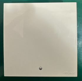
alfanar
MASA Smart Switch
SZWRBF101
Binary Switch DT
HW: 02 FW: 01.03:02.05
EFR32ZG23B
7.22.0
0x0469 (1129)
0x0004 (4)
0x0001 (1)
ZC14-25040512
2025-04-03 14:12:54
N/A
Enhanced End Node 232
Always On End Node
MASA smart switches offer seamless control for incandescent, halogen, LED, and fluorescent lights, powered by advanced Z-Wave 800 technology for secure and efficient performance.


1 - AC zero-crossing detection
AC zero-crossing detection, set to 0 to disableSize: 1 byte
Default: 1
Minimum: 0
Maximum: 1
Possible values
| From | To | Desription |
|---|---|---|
| 0 | 0 | 0 |
2 - Over-Temp Protection Threshold
Over-Temp Protection Threshold in °C, set to 0 to disableSize: 4 bytes
Default: 100
Minimum: 0
Maximum: 120
Possible values
| From | To | Desription |
|---|---|---|
| 0 | 0 | 0 |
3 - Over-Voltage Protection Threshold
Over-Voltage Protection Threshold in volt, set to 0 to disableSize: 4 bytes
Default: 270
Minimum: 0
Maximum: 280
Possible values
| From | To | Desription |
|---|---|---|
| 0 | 0 | 0 |
4 - Restore state after power failure
Restore state after power failure, set to 1 to enableSize: 1 byte
Default: 0
Minimum: 0
Maximum: 1
Possible values
| From | To | Desription |
|---|---|---|
| 0 | 0 | 0 |
5 - Indicator LED Enable /Disable
Indicator LED Enable /Disable, set to 0 to disableSize: 1 byte
Default: 1
Minimum: 0
Maximum: 1
Possible values
| From | To | Desription |
|---|---|---|
| 0 | 0 | 0 |
6 - LED Indicator Mode
LED Indicator Mode, set to 1 to LocatorSize: 1 byte
Default: 0
Minimum: 0
Maximum: 1
Possible values
| From | To | Desription |
|---|---|---|
| 0 | 0 | 0 |
7 - Factory Reset switch
Factory Reset switch, set to 0x55 to Restore factory settingSize: 1 byte
Default: 0
Minimum: 0
Maximum: 255
Possible values
| From | To | Desription |
|---|---|---|
| 0 | 0 | 0 |
8 - Disable Local Control
Disable Local Control, set to 1 to disable local controlSize: 1 byte
Default: 0
Minimum: 0
Maximum: 1
Possible values
| From | To | Desription |
|---|---|---|
| 0 | 0 | 0 |
9 - Disable Remote control
Disable Remote control, set to 1 to disable remote controlSize: 1 byte
Default: 0
Minimum: 0
Maximum: 1
Possible values
| From | To | Desription |
|---|---|---|
| 0 | 0 | 0 |
10 - Key Mode
Key ModeSize: 1 byte
Default: 0
Minimum: 0
Maximum: 4
Possible values
| From | To | Desription |
|---|---|---|
| 0 | 0 | 0 |
11 - Key1 Mode
Key1 ModeSize: 1 byte
Default: 0
Minimum: 0
Maximum: 4
Possible values
| From | To | Desription |
|---|---|---|
| 0 | 0 | 0 |
14 - On/Off State Duration
On/Off State DurationSize: 2 bytes
Default: 0
Minimum: 0
Maximum: 32767
Possible values
| From | To | Desription |
|---|---|---|
| 0 | 0 | 0 |
15 - On/Off State Duration For Key1
On/Off State Duration For Key1Size: 2 bytes
Default: 0
Minimum: 0
Maximum: 32767
Possible values
| From | To | Desription |
|---|---|---|
| 0 | 0 | 0 |
1. Place the device within the direct range of your Z-Wave gateway. 2. Power ON the device. 3. Set the main gateway to (Security/Non-Security Mode) and enable the Add/Inclusion mode (refer to the gateway''s manual for instructions). 4. Press push button for 3 consecutive clicks. 5. If adding Security S2 Authenticated mode, enter the DSK PIN or scan the Smart Start QR code (located on the as shown below image). 6. The indicator LED will blink (1 second ON & 1 second OFF simultaneously) until the inclusion process complete or timeout. 7. Successful inclusion will be confirmed by Z-Wave gateway. (Check update in the gateway APP).
1. Set the main Z-Wave Gateway into exclusion/remove mode (see the gateway’s manual). 2. Press push button for 3 consecutive clicks. 3. The indicator LED will begin blinking (1 second ON & 1 second OFF simultaneously) until the exclusion process to complete. 4. The Z-Wave gateway will confirm successful exclusion.
Please follow this procedure only if the network’s primary controller is missing or non-operational. To perform a factory reset, press any button 10 times consecutively
In the LV isolate plate, the user simply needs to disassemble the Rocker to access the DSK.
| Type | Value(s) |
|---|
| Group | Type |
|---|---|
| Heat Alarm |
|
| Power Management |
|
| System | Heartbeat |