Nice S.p.A
On/Off Control2
NICE On/Off-Control2
Binary Switch DT
HW: 05 FW: 08.00
EFR32ZG23B
7.22.2
0x010F (271)
0x0205 (517)
0x2000 (8192)
ZC14-25070530
2025-07-01 14:40:48
N/A
Enhanced End Node 232
Always On End Node
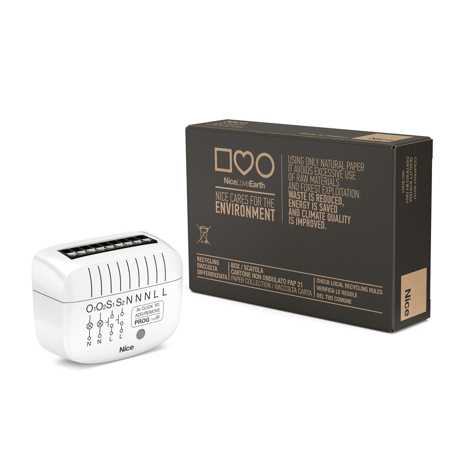
On/Off-Control 2 is designed to be installed in standard wall switch boxes or anywhere else where it's necessary to control electric devices.


1 - Restore state after power failure
This parameter determines if the device will return to the state prior to the power failure after power is restored.Size: 1 byte
Default: 1
Minimum: 0
Maximum: 1
Possible values
| From | To | Desription |
|---|---|---|
| 0 | 0 | 0 |
20 - Switch type
This parameter defines as what type the device should treat switches connected to S1 and S2 terminals.Size: 1 byte
Default: 2
Minimum: 0
Maximum: 2
Possible values
| From | To | Desription |
|---|---|---|
| 0 | 0 | 0 |
24 - Buttons orientation
This parameter enables changing inputs orientation without the need of changing electrical connections.Size: 1 byte
Default: 0
Minimum: 0
Maximum: 1
Possible values
| From | To | Desription |
|---|---|---|
| 0 | 0 | 0 |
40 - First button - scenes sent
This parameter determines which actions result in sending scene IDs assigned to them.Size: 1 byte
Default: 15
Minimum: 0
Maximum: 15
Possible values
| From | To | Desription |
|---|---|---|
| 0 | 0 | 0 |
41 - Second button - scenes sent
This parameter determines which actions result in sending scene IDs assigned to them.Size: 1 byte
Default: 15
Minimum: 0
Maximum: 15
Possible values
| From | To | Desription |
|---|---|---|
| 0 | 0 | 0 |
154 - First channel - auto off
This parameter allows to set the auto off time for the first channel. For the value 0 the functionality is disabled.Size: 2 bytes
Default: 0
Minimum: 0
Maximum: 3600
Possible values
| From | To | Desription |
|---|---|---|
| 0 | 0 | 0 |
155 - Second channel - auto off
This parameter allows to set the auto off time for the second channel. For the value 0 the functionality is disabled.Size: 2 bytes
Default: 0
Minimum: 0
Maximum: 3600
Possible values
| From | To | Desription |
|---|---|---|
| 0 | 0 | 0 |
200 - Voltage measurement
This parameter allows to set the value by which the mains voltage must change for the device to send the voltage measurement report. For the value 0 the functionality is disabled.Size: 1 byte
Default: 0
Minimum: 0
Maximum: 10
Possible values
| From | To | Desription |
|---|---|---|
| 0 | 0 | 0 |
201 - Voltage value for notification
This parameter allows to set the value that the mains voltage must exceed for the device to send the voltage notification report. For the value 0 the functionality is disabled.Size: 2 bytes
Default: 0
Minimum: 0
Maximum: 260
Possible values
| From | To | Desription |
|---|---|---|
| 0 | 0 | 0 |
202 - Outputs mode
This parameters allows you to connect both channels and control them simultaneously.Size: 1 byte
Default: 0
Minimum: 0
Maximum: 1
Possible values
| From | To | Desription |
|---|---|---|
| 0 | 0 | 0 |
Adding (Inclusion) - TheZ-Wave device learning mode enables adding the device to the existing Z-Wave network. 5.1 - Adding the device to the Z-Wave network manually 1. Place On/Off-Control2 within the direct range of your Z-Wave controller. 2. Set the main controller in the (security/non-security) add mode (for more information, see the controller manual). 3. Press quickly three times S1 or S2 switch or the PROG button. 4. If you''re adding the device in the Security S2 Authenticated mode, input the PIN Code, which is labelled on the device. The PIN Code is also an underlined part of the device specific key (DSK) labelled at the bottom of the box. 5. Wait for the adding process to end. 6. Successful adding is confirmed by the Z-Wave controller message and the green LED diode when adding the device to the non-secure, S0, S2 Unauthenticated mode or magenta LED diode when adding the device to the S2 Authenticated mode.
To remove the device from the Z-Wave network: 1. Place On/Off-Control2 within the direct range of your Z-Wave controller. 2. Set the main controller in the (security/non-security) remove mode (for more information, see the controller manual). 3. Press quickly three times S1 or S2 switch or the PROG button. 4. Wait for the removing process to end. 5. Successful removing is confirmed with the Z-Wave controller message and the red LED diode.
7.2 - Resetting On/Off-Control2 1. Switch off the mains voltage (disable the fuse). 2. Remove On/Off-Control2 from the wall switch box. 3. Switch on the mains voltage. 4. Press and hold the PROG-button to enter the menu. 5. Wait for the visual LED indicator to glow yellow. 6. Quickly release and click the PROG-button again. 7. After a few seconds the device is restarted, which is signalled with the red LED indicator color.
If you''re adding the device in the Security S2 Authenticated mode, input the PIN Code, which is labelled on the device. The PIN Code is also an underlined part of the device specific key (DSK) labelled at the bottom of the box.
| Group | Type |
|---|---|
| Power Management |
|
| System | HW status: System hardware failure (manufacturer proprietary failure code provided) |